Chapter 5: Advanced Motherboard Setup
Internal Speaker
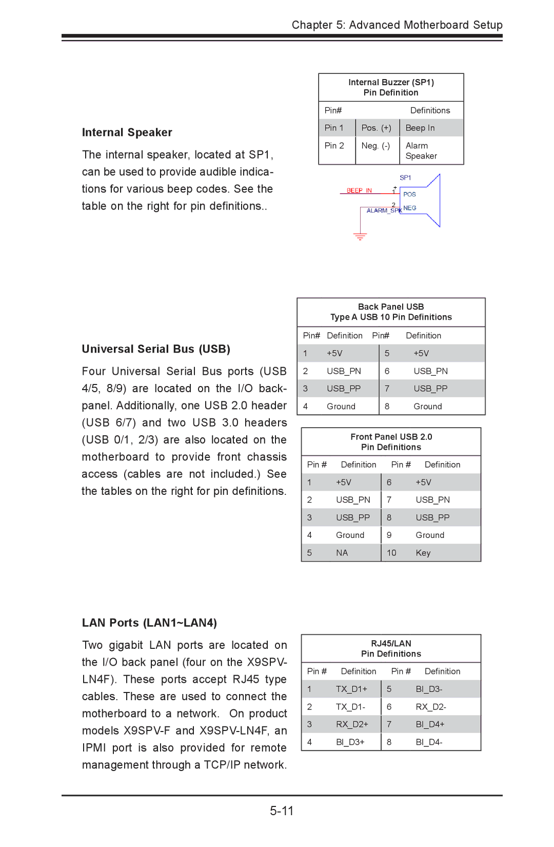
The internal speaker, located at SP1, can be used to provide audible indica- tions for various beep codes. See the table on the right for pin definitions..
Internal Buzzer (SP1)
Pin Definition
Pin# |
|
|
| Definitions |
Pin 1 |
| Pos. (+) |
| Beep In |
|
| |||
Pin 2 |
| Neg. |
| Alarm |
|
| |||
|
|
|
| Speaker |
|
|
|
|
|
Universal Serial Bus (USB)
Four Universal Serial Bus ports (USB 4/5, 8/9) are located on the I/O back- panel. Additionally, one USB 2.0 header (USB 6/7) and two USB 3.0 headers (USB 0/1, 2/3) are also located on the motherboard to provide front chassis access (cables are not included.) See the tables on the right for pin definitions.
Back Panel USB
Type A USB 10 Pin Definitions
| Pin# | Definition Pin# Definition | ||||
1 | +5V |
|
| +5V | ||
5 | ||||||
2 | USB_PN | 6 | USB_PN | |||
3 | USB_PP | 7 | USB_PP | |||
4 | Ground | 8 | Ground | |||
|
|
|
|
|
| |
|
|
|
| |||
|
| Front Panel USB 2.0 |
| |||
|
| Pin Definitions |
| |||
| Pin # | Definition |
| Pin # | Definition |
|
| 1 | +5V |
| +5V |
| |
|
| 6 |
| |||
| 2 | USB_PN |
|
| USB_PN |
|
|
| 7 |
| |||
| 3 | USB_PP |
|
| USB_PP |
|
|
| 8 |
| |||
| 4 | Ground |
|
| Ground |
|
|
| 9 |
| |||
| 5 | NA |
|
| Key |
|
|
| 10 |
| |||
|
|
|
|
|
|
|
LAN Ports (LAN1~LAN4)
Two gigabit LAN ports are located on the I/O back panel (four on the X9SPV- LN4F). These ports accept RJ45 type cables. These are used to connect the motherboard to a network. On product models
RJ45/LAN
Pin Definitions
Pin # | Definition | Pin # | Definition |
1 | TX_D1+ |
| BI_D3- |
5 | |||
2 | TX_D1- |
| RX_D2- |
6 | |||
3 | RX_D2+ |
| BI_D4+ |
7 | |||
4 | BI_D3+ |
| BI_D4- |
8 | |||
|
|
|
|