SUPERSERVER
SGPIO
The two headers labeled
SGPIO Header
Pin Definitions
Pin# | Defi nition | Pin # | Defi nition |
1 | NC | 2 | NC |
3 | Ground |
| Data |
4 | |||
5 | Load |
| Ground |
6 | |||
7 | NC |
| NC |
8 | |||
|
|
|
|
Note: NC indicates no connection.
5-9 Jumper Settings
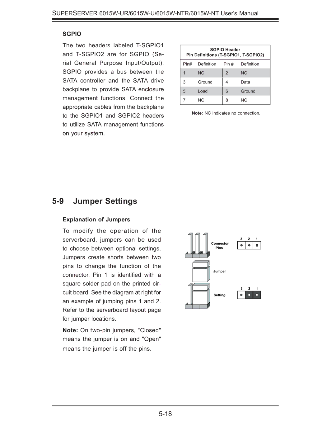
Explanation of Jumpers
To modify the operation of the serverboard, jumpers can be used to choose between optional settings. Jumpers create shorts between two pins to change the function of the connector. Pin 1 is identifi ed with a square solder pad on the printed cir- cuit board. See the diagram at right for an example of jumping pins 1 and 2. Refer to the serverboard layout page for jumper locations.
Note: On
3 2 1
Connector
Pins
Jumper
3 2 1
Setting