SUPER
2-6 Onboard Indicators
GLAN1/GLAN2 LEDs
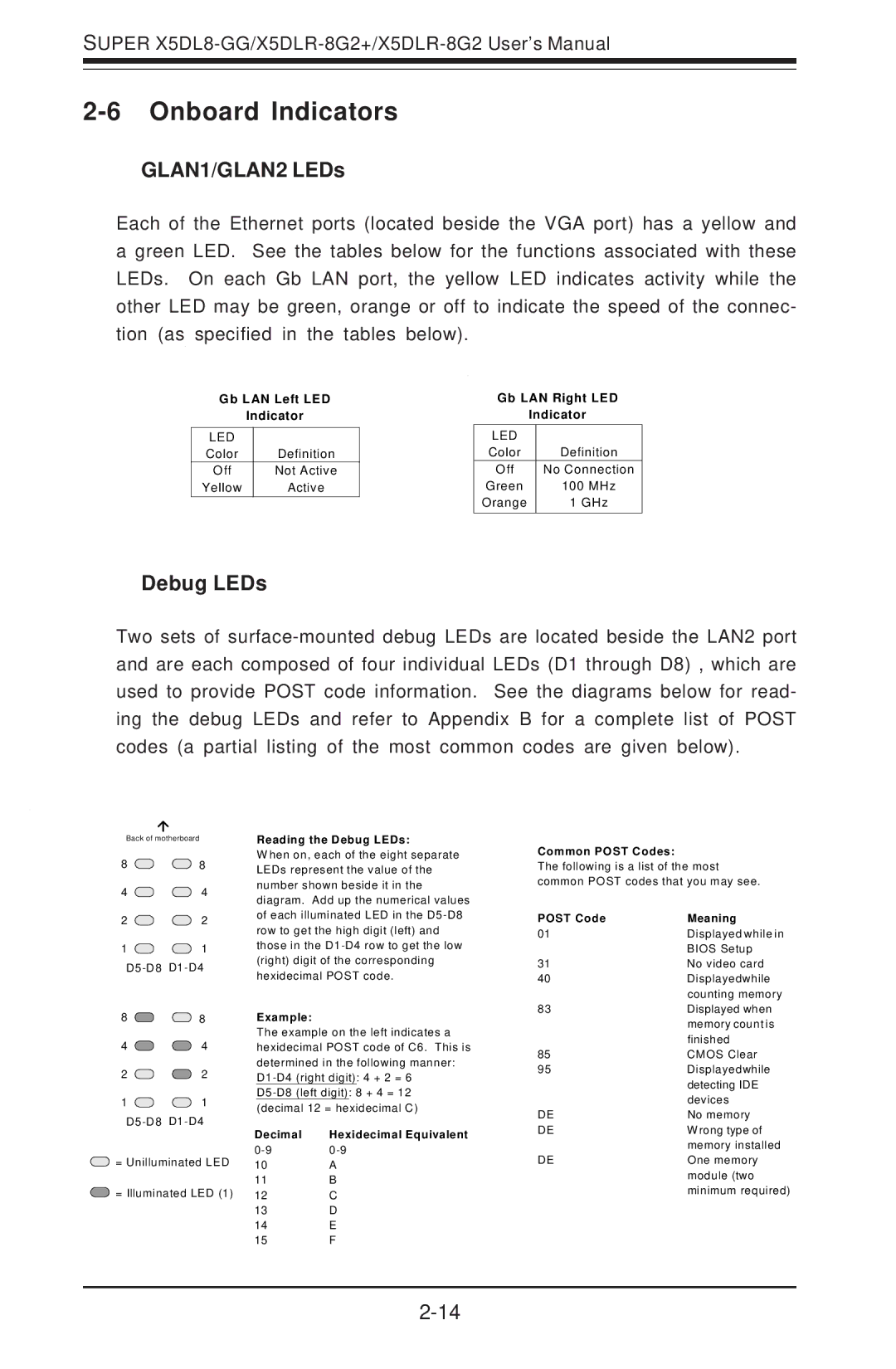
Each of the Ethernet ports (located beside the VGA port) has a yellow and a green LED. See the tables below for the functions associated with these LEDs. On each Gb LAN port, the yellow LED indicates activity while the other LED may be green, orange or off to indicate the speed of the connec- tion (as specified in the tables below).
Gb LAN Left LED
Indicator
LED |
|
Color | Definition |
Off | Not Active |
Yellow | Active |
Gb LAN Right LED
Indicator
LED |
|
Color | Definition |
Off | No Connection |
Green | 100 MHz |
Orange | 1 GHz |
|
|
Debug LEDs
Two sets of
Back of motherboard
8 ![]()
![]() 8
8
4 ![]()
![]() 4
4
2 ![]()
![]() 2
2
1 ![]()
![]() 1
1
8 ![]()
![]() 8
8
4 ![]()
![]() 4
4
2 ![]()
![]() 2
2
1 ![]()
![]() 1
1
Reading the Debug LEDs:
W hen on, each of the eight separate LEDs represent the value of the number shown beside it in the diagram. Add up the numerical values of each illuminated LED in the
Example:
The example on the left indicates a hexidecimal POST code of C6. This is determined in the following manner:
Common POST Codes:
The following is a list of the most common POST codes that you may see.
POST Code | Meaning |
01Displayed while in BIOS Setup
31 | No video card |
40 | Displayedwhile |
| counting memory |
83Displayed when memory count is finished
85 | CMOS Clear |
95Displayedwhile detecting IDE devices
DE | No memory |
Decimal | Hexidecimal Equivalent | |
| ||
= Unilluminated LED | ||
10 | A | |
= Illuminated LED (1) | 11 | B |
12 | C |
13D
14E
15F
DE | W rong type of |
| memory installed |
DE | One memory |
| module (two |
| minimum required) |