Chapter 2: Installation
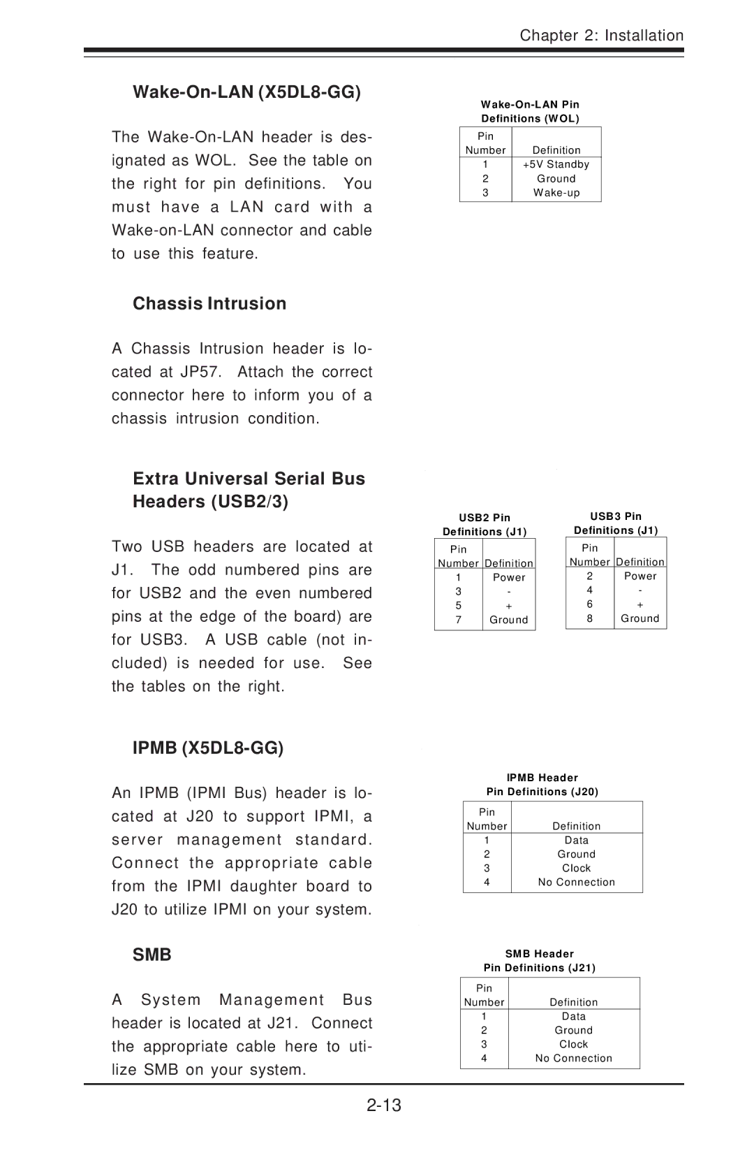
Wake-On-LAN (X5DL8-GG)
The
Chassis Intrusion
A Chassis Intrusion header is lo- cated at JP57. Attach the correct connector here to inform you of a chassis intrusion condition.
Extra Universal Serial Bus Headers (USB2/3)
Pin |
|
Number | Definition |
1+5V Standby
2Ground
3W
Two USB headers are located at J1. The odd numbered pins are for USB2 and the even numbered pins at the edge of the board) are for USB3. A USB cable (not in- cluded) is needed for use. See the tables on the right.
USB2 Pin
Definitions (J1)
Pin |
|
Number | Definition |
1 | Power |
3 | - |
5 | + |
7 | Ground |
|
|
USB3 Pin
Definitions (J1)
Pin |
|
Number | Definition |
2 | Power |
4 | - |
6 | + |
8 | Ground |
|
|
IPMB (X5DL8-GG)
An IPMB (IPMI Bus) header is lo- cated at J20 to support IPMI, a server management standard. Connect the appropriate cable from the IPMI daughter board to J20 to utilize IPMI on your system.
SMB
A System Management Bus header is located at J21. Connect the appropriate cable here to uti- lize SMB on your system.
IPMB Header
Pin Definitions (J20)
Pin |
|
Number | Definition |
1 | Data |
2 | Ground |
3 | Clock |
4 | No Connection |
|
|
SMB Header
Pin Definitions (J21)
Pin |
|
Number | Definition |
1 | Data |
2 | Ground |
3 | Clock |
4 | No Connection |
|
|