SUPER
Floppy Connector
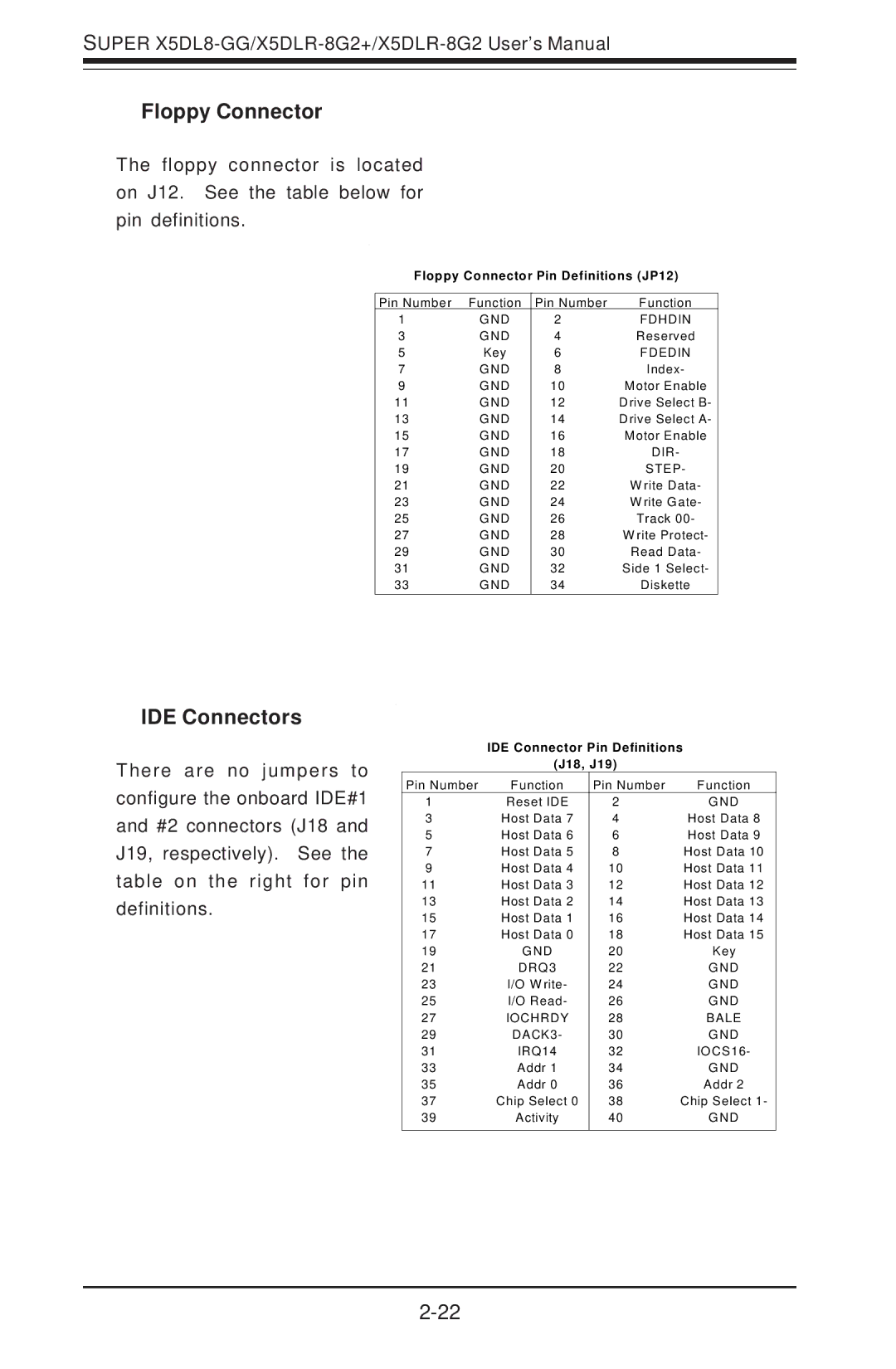
The floppy connector is located on J12. See the table below for pin definitions.
Floppy Connector Pin Definitions (JP12)
Pin Number | Function | Pin Number | Function |
1 | GND | 2 | FDHDIN |
3 | GND | 4 | Reserved |
5 | Key | 6 | FDEDIN |
7 | GND | 8 | Index- |
9 | GND | 10 | Motor Enable |
11 | GND | 12 | Drive Select B- |
13 | GND | 14 | Drive Select A- |
15 | GND | 16 | Motor Enable |
17 | GND | 18 | DIR- |
19 | GND | 20 | STEP- |
21 | GND | 22 | W rite Data- |
23 | GND | 24 | W rite Gate- |
25 | GND | 26 | Track 00- |
27 | GND | 28 | W rite Protect- |
29 | GND | 30 | Read Data- |
31 | GND | 32 | Side 1 Select- |
33 | GND | 34 | Diskette |
IDE Connectors
There are no jumpers to configure the onboard IDE#1 and #2 connectors (J18 and J19, respectively). See the table on the right for pin definitions.
IDE Connector Pin Definitions
(J18, J19)
Pin Number | Function | Pin Number | Function |
1 | Reset IDE | 2 | GND |
3 | Host Data 7 | 4 | Host Data 8 |
5 | Host Data 6 | 6 | Host Data 9 |
7 | Host Data 5 | 8 | Host Data 10 |
9 | Host Data 4 | 10 | Host Data 11 |
11 | Host Data 3 | 12 | Host Data 12 |
13 | Host Data 2 | 14 | Host Data 13 |
15 | Host Data 1 | 16 | Host Data 14 |
17 | Host Data 0 | 18 | Host Data 15 |
19 | GND | 20 | Key |
21 | DRQ3 | 22 | GND |
23 | I/O W rite- | 24 | GND |
25 | I/O Read- | 26 | GND |
27 | IOCHRDY | 28 | BALE |
29 | DACK3- | 30 | GND |
31 | IRQ14 | 32 | IOCS16- |
33 | Addr 1 | 34 | GND |
35 | Addr 0 | 36 | Addr 2 |
37 | Chip Select 0 | 38 | Chip Select 1- |
39 | Activity | 40 | GND |
|
|
|
|