SUPER MICRO Computer SUPER X5DLR-8G2+, SUPER X5DL8-GG Front Control Panel, JF1/JF2 Header Pins

Models: SUPER X5DLR-8G2+ SUPER X5DL8-GG SUPER X5DLR-8G2

1 90
Download 90 pages 57.28 Kb
Page 31
Image 31

Chapter 2: Installation

Front Control Panel

JF1 contains header pins for various front control panel connectors. These connectors are designed for use with Supermicro server chassis. See Figure 2-4 for the pin locations of the various front control panel buttons and LED indicators. Refer to the following section for descriptions and pin definitions. JF2 is an additional row of headers that provides connectors for additional functions, as noted below.

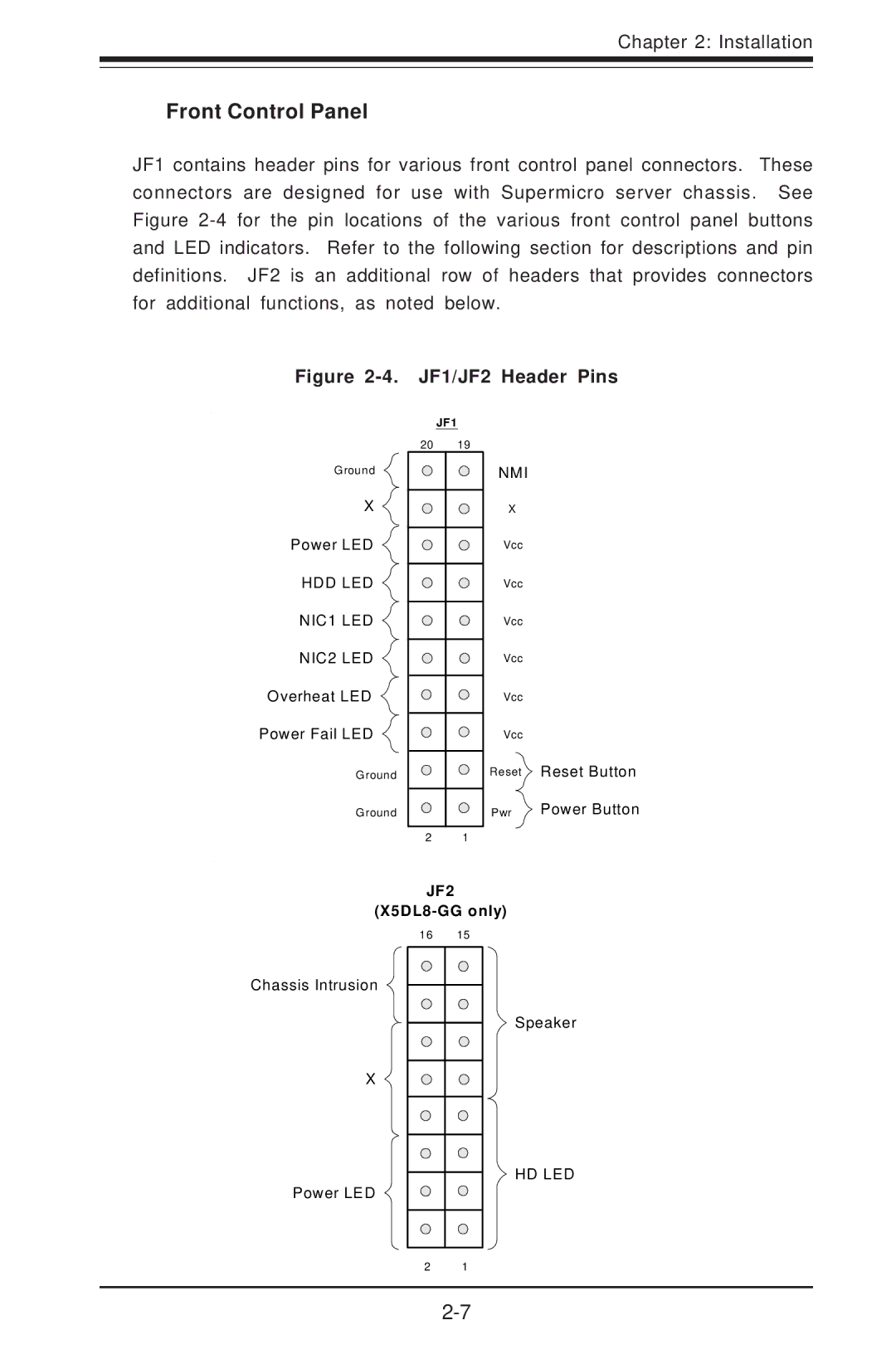
Figure 2-4. JF1/JF2 Header Pins

Ground

X

Power LED

HDD LED

NIC1 LED

NIC2 LED

Overheat LED

Power Fail LED

Ground

Ground


JF1

20

19


NMI


X


Vcc

Vcc

Vcc

Vcc

Vcc

Vcc

Reset Reset Button

Pwr Power Button

2 1

JF2

(X5DL8-GG only)

16

15

Chassis Intrusion


X


Speaker

Power LED

HD LED

2 1

2-7

Page 31
Image 31
SUPER MICRO Computer SUPER X5DLR-8G2+, SUPER X5DL8-GG user manual Front Control Panel, JF1/JF2 Header Pins