SUPER
Figure 2-2. Installing and Removing DIMMs
To Install:
Insert the module vertically and press down until it snaps into place. Pay atten- tion to the notch on the bot- tom of the module.
To Remove:
Use your thumbs to gently push near the edge of both ends of
the module. This should release it from the slot.
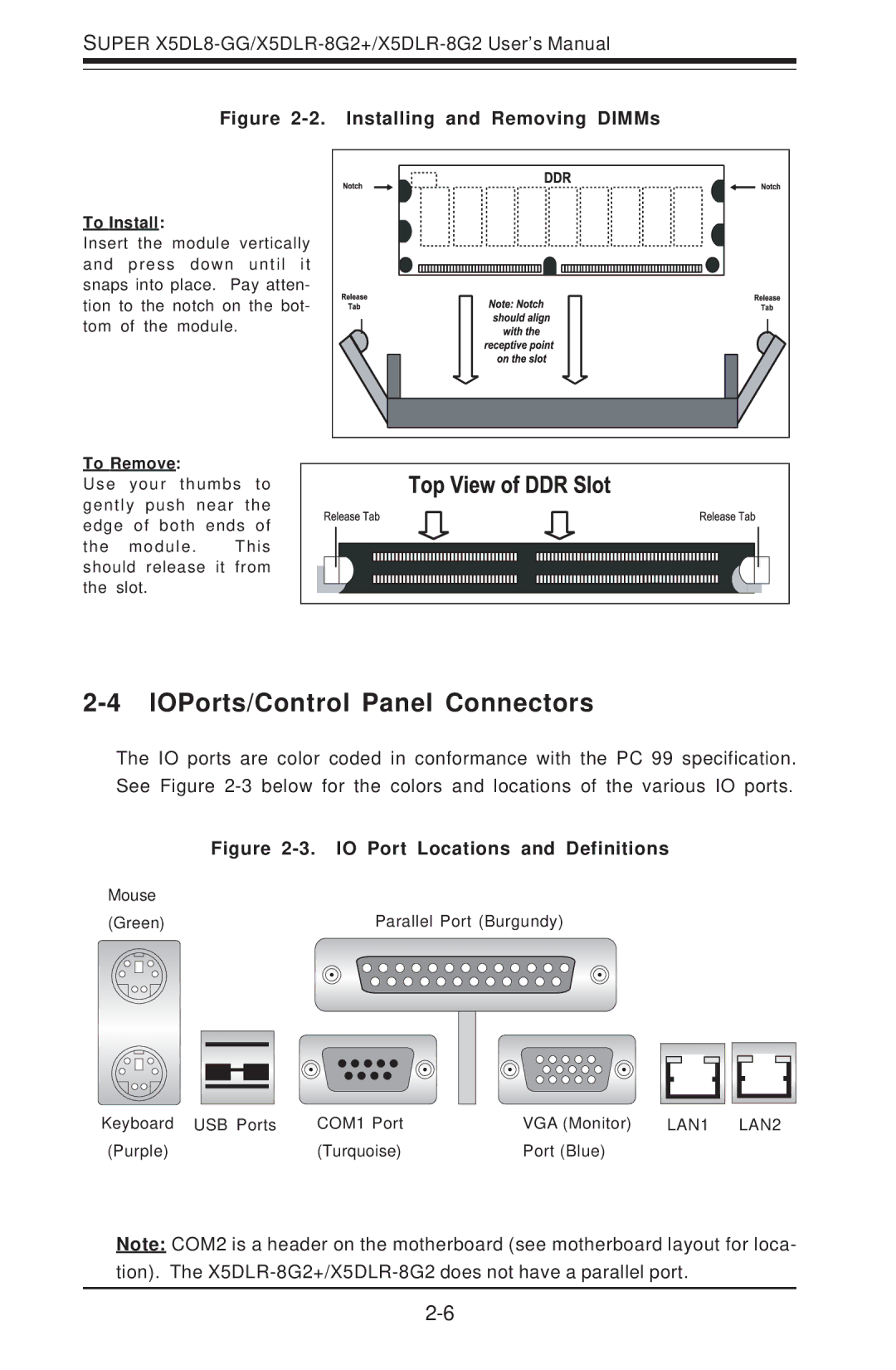
2-4 IOPorts/Control Panel Connectors
The IO ports are color coded in conformance with the PC 99 specification. See Figure
|
|
| Figure | ||||||||||
Mouse |
|
|
|
|
|
|
|
|
|
|
| ||
(Green) |
|
|
|
| Parallel Port (Burgundy) | ||||||||
|
|
|
|
|
|
|
|
|
|
|
|
|
|
|
|
|
|
|
|
|
|
|
|
|
|
|
|
|
|
|
|
|
|
|
|
|
|
|
|
|
|
|
|
|
|
|
|
|
|
|
|
|
|
|
|
|
|
|
|
|
|
|
|
|
|
|
|
|
|
|
|
|
|
|
|
|
|
|
|
|
|
|
|
|
|
|
|
|
|
|
|
|
|
|
|
|
|
|
|
|
|
|
|
|
|
|
|
|
|
|
|
|
|
|
|
|
|
|
|
|
|
|
|
|
|
|
|
|
|
|
|
|
|
|
|
|
|
|
|
|
|
|
|
|
|
|
|
|
|
|
|
|
|
|
|
|
|
|
|
|
|
|
|
|
|
|
|
Keyboard USB Ports | COM1 Port | VGA (Monitor) | LAN1 LAN2 |
(Purple) | (Turquoise) | Port (Blue) |
|
Note: COM2 is a header on the motherboard (see motherboard layout for loca- tion). The