SUPER
2-5 Connecting Cables
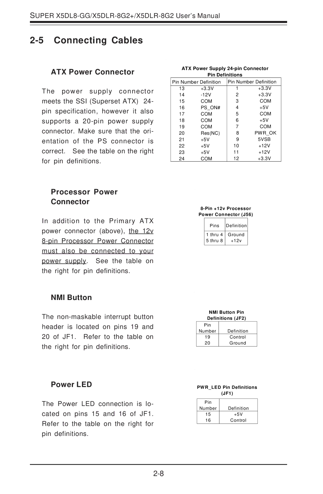
ATX Power Connector
The power supply connector meets the SSI (Superset ATX) 24- pin specification, however it also supports a
ATX Power Supply
Pin Definitions
Pin Number Definition | Pin Number Definition | ||
13 | +3.3V | 1 | +3.3V |
14 | 2 | +3.3V | |
15 | COM | 3 | COM |
16 | PS_ON# | 4 | +5V |
17 | COM | 5 | COM |
18 | COM | 6 | +5V |
19 | COM | 7 | COM |
20 | Res(NC) | 8 | PWR_OK |
21 | +5V | 9 | 5VSB |
22 | +5V | 10 | +12V |
23 | +5V | 11 | +12V |
24 | COM | 12 | +3.3V |
Processor Power
Connector
In addition to the Primary ATX power connector (above), the 12v
NMI Button
The
Power LED
The Power LED connection is lo- cated on pins 15 and 16 of JF1. Refer to the table on the right for pin definitions.
Pins Definition
1 thru 4 | Ground |
5 thru 8 | +12v |
NMI Button Pin
Definitions (JF2)
Pin
Number Definition
19Control
20Ground
PWR_LED Pin Definitions
(JF1)
Pin |
|
Number | Definition |
15 | +5V |
16 | Control |