Encoder Board NTSC
Set-up
1.Switch off power. Place encoder board on service extender. Genlock camera with black burst signal. Switch on power.
2.Connect oscilloscope via a vectorscope terminated with 75Ohm to the CVBS output of the camera.
3.Switch on colour bar.
Black balance
4.Turn chroma potentiometer R4 on encoder board fully clockwise (max. chroma).
5.Adjust the I and Q balance potentiometers for minimum unbalance in black.
Measure at:
CVBS out
Adjust with:
ZR203
ZR206
Required result:
Smallest possible
dot in centre of
vectorscope
6. Turn chroma potentiometer R4 on encoder board fully counterclockwise (zero chrominance).
CVBS amplitude
7. Adjust the CVBS gain potentiometer to obtain an output amplitude of 549mV (77 IRE).
Measure at:
CVBS out
Adjust with:
R14
Required result:
549mV
(77 IRE)
Correct:
0.1V10µS
100
90
10
0%
![]() VA+549mV
VA+549mV
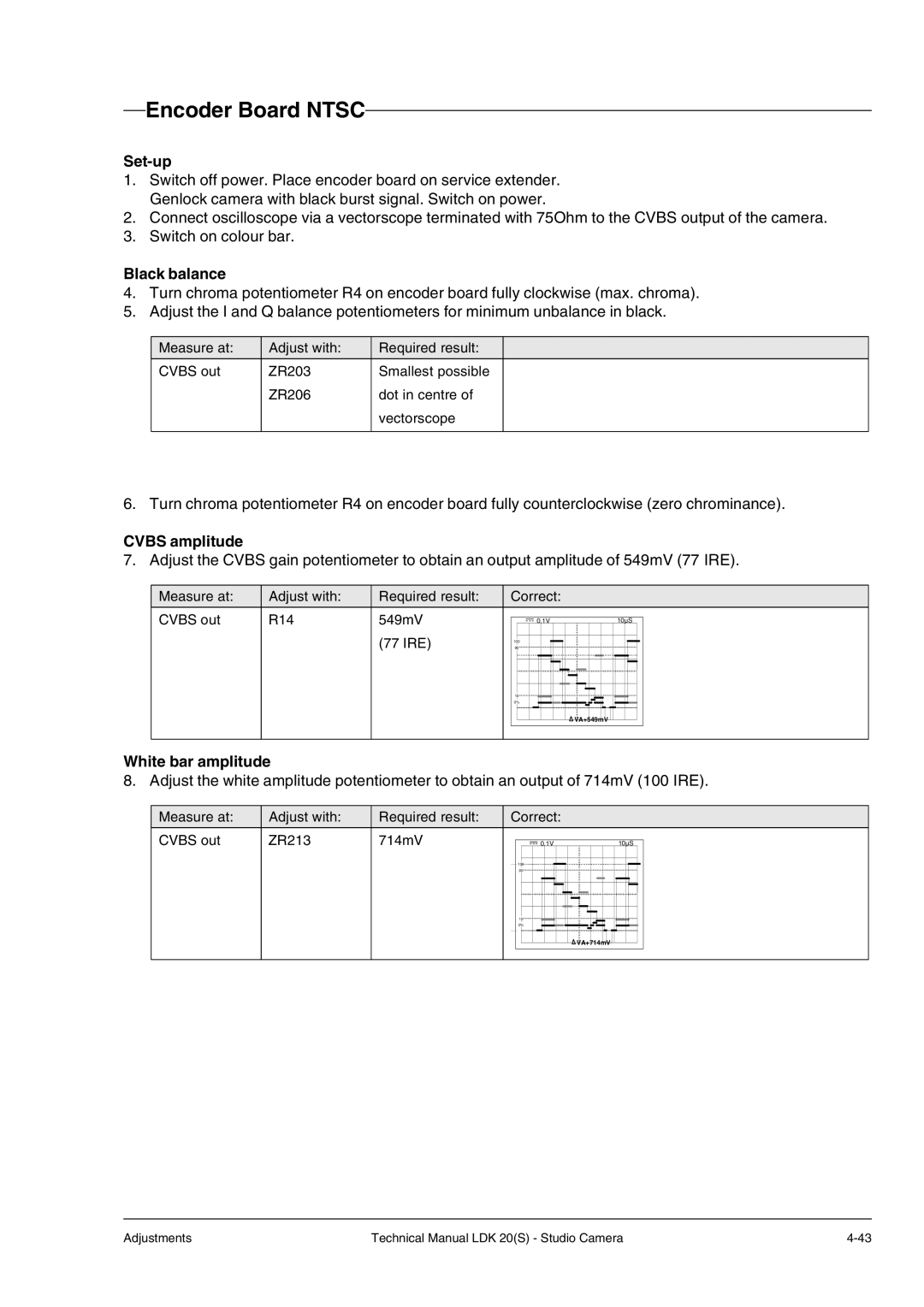
White bar amplitude
8. Adjust the white amplitude potentiometer to obtain an output of 714mV (100 IRE).
Measure at:
CVBS out
Adjust with:
ZR213
Required result:
714mV
Correct:
0.1V10µS
100
90
10
0%
![]() VA+714mV
VA+714mV
Adjustments | Technical Manual LDK 20(S) - Studio Camera |