Symbol Colour | Explanation |
|
|
Red | High voltage terminal at which a | ||
| voltage, with respect to an other | ||
| terminal, exists or may be | ||
| adjusted to 1000V or more. | ||
Yellow/Black | Live part. |
|
|
Yellow/Black | This marking indicates that the | ||
| operator must refer to an | ||
| explanation | in the | Instruction |
| Manual, or that a specific | ||
| component must be replaced by | ||
| the component specified in the | ||
| documentation for safety | ||
| reasons. |
|
|
White/Black | Protective | earth | (ground) |
| terminal. |
|
|
Cathode ray tubes
Components marked ![]() on the circuit diagram are critical for safety and include those specified to comply with
on the circuit diagram are critical for safety and include those specified to comply with
When servicing units that use cathode ray tubes (CRTs), the cathode ray tubes themselves, the high voltage circuits and related circuits are specifically chosen so that they comply with recognized codes pertaining to
Consequently, when servicing, replace the cathode ray tubes and other parts with specified parts only. Do not attempt to modify these circuits as any unauthorized modification can increase the high voltage value and cause
Handle the cathode ray tube only when wearing shatterproof goggles and after discharging the high voltage completely.
Earthing
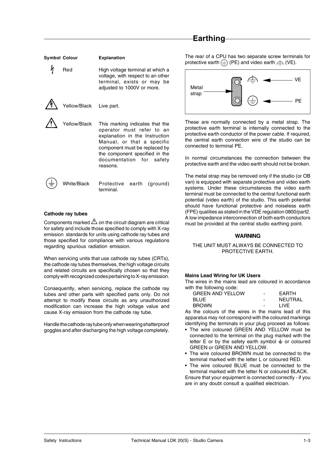
The rear of a CPU has two separate screw terminals for
protective earth ![]() (PE) and video earth
(PE) and video earth ![]() (VE).
(VE).
VE
Metal strap
PE
These are normally connected by a metal strap. The protective earth terminal is internally connected to the protective earth conductor of the power cable. If required, the central earth connection wire of the studio can be connected to terminal PE.
In normal circumstances the connection between the protective earth and the video earth should not be broken.
The metal strap may be removed only if the studio (or OB van) is equipped with separate protective and video earth systems. Under these circumstances the video earth terminal must be connected to the central functional earth potential (video earth) of the studio. This earth potential should have functional protective and noiseless earth (FPE) qualities as stated in the VDE regulation 0800/part2. A low impedance interconnection of both earth conductors must be provided at the central studio earthing point.
WARNING
THE UNIT MUST ALWAYS BE CONNECTED TO
PROTECTIVE EARTH.
Mains Lead Wiring for UK Users
The wires in the mains lead are coloured in accordance with the following code:
GREEN AND YELLOW | - | EARTH |
BLUE | - | NEUTRAL |
BROWN | - | LIVE |
As the colours of the wires in the mains lead of this apparatus may not correspond with the coloured markings identifying the terminals in your plug proceed as follows:
•The wire coloured GREEN AND YELLOW must be connected to the terminal on the plug marked with the letter E or by the safety earth symbol ![]() or coloured GREEN or GREEN AND YELLOW.
or coloured GREEN or GREEN AND YELLOW.
•The wire coloured BROWN must be connected to the terminal marked with the letter L or coloured RED.
•The wire coloured BLUE must be connected to the terminal marked with the letter N or coloured BLACK.
Ensure that your equipment is connected correctly - if you are in any doubt consult a qualified electrician.
Safety Instructions | Technical Manual LDK 20(S) - Studio Camera |