Sync./Shading Board
8.On connector B of the service extender remove the short circuits on the input to Video Processor 1 Board by disconnecting the jumpers from B7 to B9, B11 to B13 and B17 to B19,
Reconnect | A6 to B6 |
| A7 to B7 |
| A9 to B9 |
| A11 to B11 |
| A12 to B12 |
| A13 to B13 |
| A15 to B15 |
| A17 to B17 |
| A19 to B19 on connector B of the service extender. |
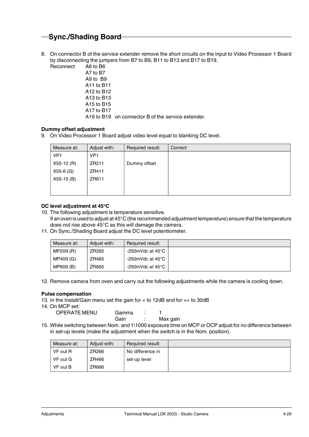
Dummy offset adjustment
9. On Video Processor 1 Board adjust video level equal to blanking DC level.
Measure at:
VP1
Adjust with:
VP1
ZR211
ZR411
ZR611
Required result:
Dummy offset
Correct:
DC level adjustment at 45oC
10.The following adjustment is temperature sensitive.
If an oven is used to adjust at 45°C (the recommended adjustment temperature) ensure that the temperature does not rise above 45°C as this will damage the camera.
11.On Sync./Shading Board adjust the DC level potentiometer.
Measure at:
MP209 (R)
MP409 (G)
MP609 (B)
Adjust with:
ZR265
ZR465
ZR665
Required result:
12. Remove camera from oven and carry out the following adjustments while the camera is cooling down.
Pulse compensation
13.In the Install/Gain menu set the gain for + to 12dB and for ++ to 30dB
14.On MCP set:
OPERATE MENU | Gamma | : | 1 |
| Gain | : | Max gain |
15.While switching between Nom. and 1\1000 exposure time on MCP or OCP adjust for no difference between in
Measure at:
VF out R
VF out G
VF out B
Adjust with:
ZR266
ZR466
ZR666
Required result:
No difference in
Adjustments | Technical Manual LDK 20(S) - Studio Camera |
