Analogue Ch1-Ch2
Two analogue channels (AN 0 and AN 1) are available from the base station to the camera via the triax cable and can be used to transmit L.F. signals. For example, joystick control or pan and tilt. The input signals are applied to the Auxiliary connector of the base station. The output signals are available on the Auxiliary connector of the camera. The input signal and output signal voltage is between 0 and 5Vdc.
The AN 1 channel is sometimes used for switching the aspect ratio. This is selected by means of the software. See next chapter for instructions.
Dipswitch Settings
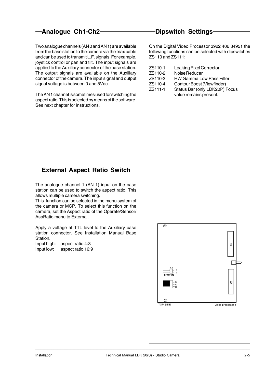
On the Digital Video Processor 3922 406 84951 the following functions can be selected with dipswitches ZS110 and ZS111:
value remains present.
External Aspect Ratio Switch
The analogue channel 1 (AN 1) input on the base station can be used to switch the aspect ratio. This allows multiple camera switching.
This function can be selected in the menu system of the camera or MCP. To select this function on the camera, set the Aspect ratio of the Operate/Sensor/ AspRatio menu to External.
Apply a voltage at TTL level to the Auxiliary base station connector. See Installation Manual Base Station.
Input high: | aspect ratio 4:3 |
Input low: | aspect ratio 16:9 |
|
| X55 |
X4 |
|
|
| 2 |
|
TEST IN | 1 |
|
|
| |
| B | X56 |
| A | |
|
| |
| C |
|
TOP SIDE |
| Video processor 1 |
Installation | Technical Manual LDK 20(S) - Studio Camera |