Encoder Board NTSC
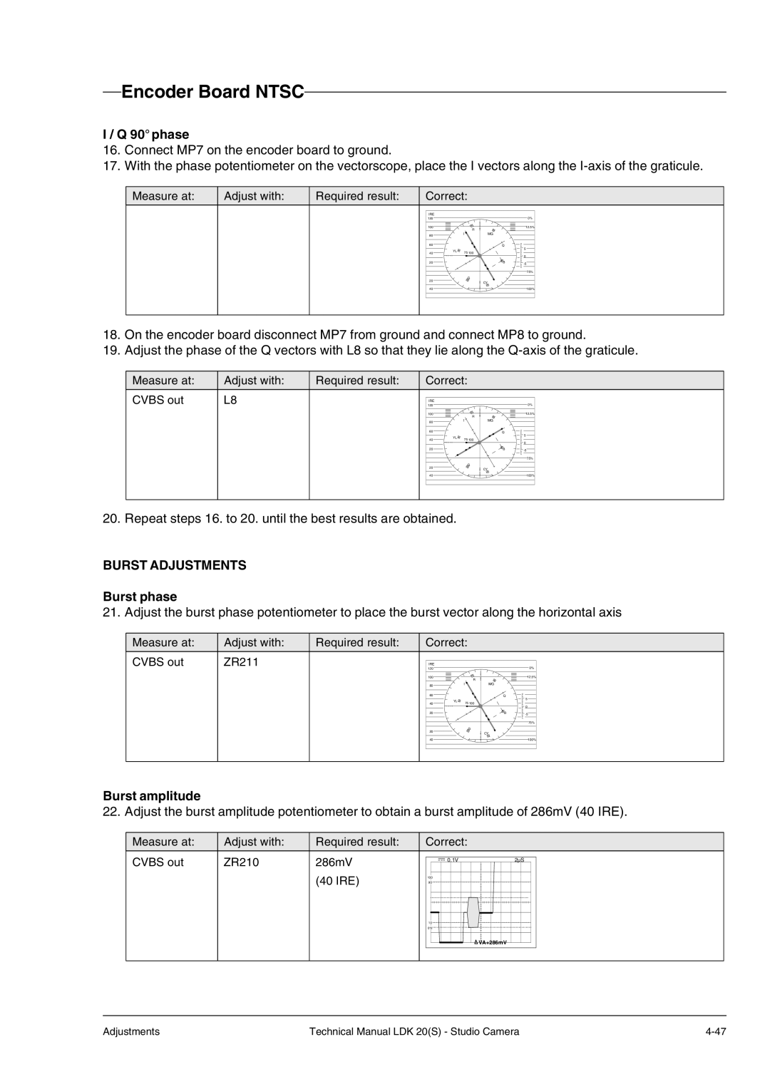
I / Q 90° phase
16.Connect MP7 on the encoder board to ground.
17.With the phase potentiometer on the vectorscope, place the I vectors along the
Measure at:
Adjust with:
Required result:
Correct: |
| ||
IRE |
|
|
|
120 |
|
| 0% |
100 |
| R | 12.5% |
|
|
| |
80 | I | MG |
|
|
|
| |
60 |
| Q | 5 |
| YL |
| |
40 | 75 100 |
| |
| 0 | ||
|
|
| |
20 |
| B | |
|
|
| 75% |
20 |
| G |
|
| CY |
| |
40 |
|
| 100% |
18.On the encoder board disconnect MP7 from ground and connect MP8 to ground.
19.Adjust the phase of the Q vectors with L8 so that they lie along the
Measure at:
CVBS out
Adjust with:
L8
Required result:
Correct: |
| ||
IRE |
|
|
|
120 |
|
| 0% |
100 |
| R | 12.5% |
|
|
| |
80 | I | MG |
|
60 |
| Q | 5 |
| YL |
| |
40 | 75 100 |
| |
| 0 | ||
|
|
| |
20 |
| B | |
|
|
| 75% |
20 |
| G |
|
| CY |
| |
|
|
| |
40 |
|
| 100% |
20. Repeat steps 16. to 20. until the best results are obtained.
BURST ADJUSTMENTS
Burst phase
21. Adjust the burst phase potentiometer to place the burst vector along the horizontal axis
Measure at:
CVBS out
Adjust with:
ZR211
Required result:
Correct: |
| ||
IRE |
|
|
|
120 |
|
| 0% |
100 |
| R | 12.5% |
|
|
| |
80 | I | MG |
|
|
|
| |
60 |
| Q | 5 |
| YL |
| |
40 | 75 100 |
| |
| 0 | ||
|
|
| |
20 |
| B | |
|
|
| 75% |
20 |
| G |
|
| CY |
| |
|
|
| |
40 |
|
| 100% |
Burst amplitude
22. Adjust the burst amplitude potentiometer to obtain a burst amplitude of 286mV (40 IRE).
Measure at:
CVBS out
Adjust with:
ZR210
Required result:
286mV
(40 IRE)
Correct: |
|
0.1V | 2µS |
100 |
|
90 |
|
10 |
|
0% |
|
| VA+286mV |
Adjustments | Technical Manual LDK 20(S) - Studio Camera |