Method 3 : Antenna + DVD
You can record
Connections
•Compared to standard interlaced video, progressive scan doubles the amount of video beam lines fed to your TV, resulting in a more stable,
•Consumers should note that not all high definition televi- sion sets are fully compatible with this product and may cause artifacts to be displayed in the picture. If you experi- ence 480 progressive scan picture problems, it is recom- mended that you switch the connection to the ‘standard definition’ output. If there are questions regarding TV set compatibility with this unit, please contact our customer service center.
Method 1 : Connecting to a video input jack
Connect a video(yellow) cable between the VIDEO (yellow) OUT jack on DVD
•You will enjoy regular quality images.
•Connect audio cables (white and red) between the ANA- LOG AUDIO OUT jack on the DVD
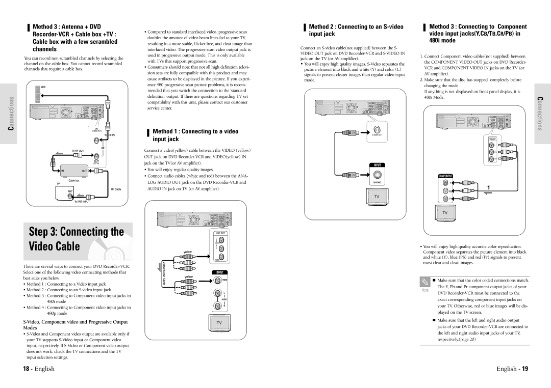
Method 2 : Connecting to an S-video input jack
Connect an
•You will enjoy high quality images.
Method 3 : Connecting to Component video input jacks(Y,CB/TB,CR/PB) in 480i mode
1.Connect Component video cables(not supplied) between the COMPONENT VIDEO OUT jacks on DVD Recorder- VCR and COMPONENT VIDEO IN jacks on the TV (or AV amplifier).
2.Make sure that the disc has stopped completely before changing the mode.
If anything is not displayed on front panel display, it is 480i Mode.
Connections
Step 3: Connecting the Video Cable
•You will enjoy high quality accurate color reproduction. Component video separates the picture element into black and white (Y), blue (Pb) and red (Pr) signals to present most clear and clean images.
There are several ways to connect your DVD
•Method 1 : Connecting to a Video input jack
•Method 2 : Connecting to an
•Method 3 : Connecting to Component video input jacks in 480i mode
•Method 4 : Connecting to Component video input jacks in 480p mode
S-Video, Component video and Progressive Output Modes
•
Note
Make sure that the color coded connections match.
The Y, Pb and Pr component output jacks of your
DVD
Make sure that the left and right audio output jacks of your DVD
18 - English | English - 19 |