8
1.3Rear Panel Connectors
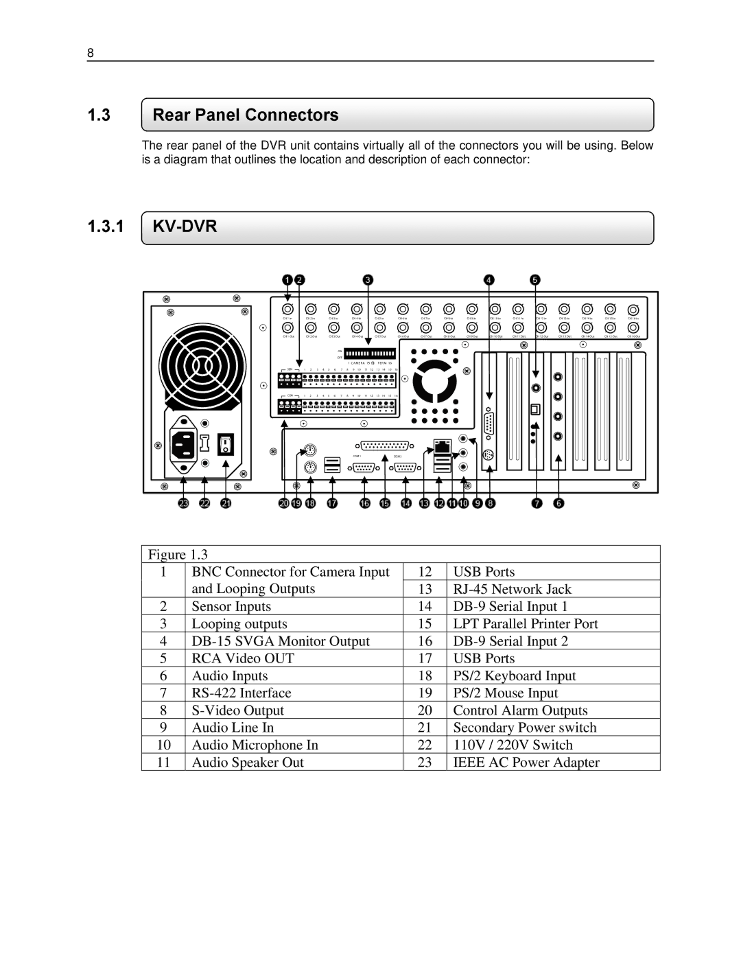
The rear panel of the DVR unit contains virtually all of the connectors you will be using. Below is a diagram that outlines the location and description of each connector:
1.3.1KV-DVR
CH 1 in |
| CH 2 in |
|
| CH 3 in |
| CH 4 in |
|
| CH 5 in |
| CH 6 in | CH 7 in | CH 8 in | CH 9 in | CH 10 in | CH 11 in | CH 12 in | CH 13 in | CH 14 in | CH 15 in | CH 16 in | ||||
CH 1 Out |
| CH 2 Out |
| CH 3 Out |
| CH 4 Out |
|
| CH 5 Out |
| CH 6 Out | CH 7 Out | CH 8 Out | CH 9 Out | CH 10 Out | CH 11 Out | CH 12 Out | CH 13 Out | CH 14 Out | CH 15 Out | CH 16 Out | |||||
|
|
|
|
|
|
| ON |
|
|
|
|
|
|
|
|
|
|
|
|
|
|
|
|
|
|
|
|
|
|
|
|
|
| OFF |
|
|
|
|
|
|
|
|
|
|
|
|
|
|
|
|
|
|
|
|
|
|
|
|
|
|
| 1 CAMERA 75 |
| TERM 16 |
|
|
|
|
|
|
|
|
|
|
| |||||
SEN | 1 | 2 | 3 | 4 | 5 | 6 | 7 | 8 | 9 | 10 | 11 | 12 | 13 | 14 | 15 | 16 |
|
|
|
|
|
|
|
|
|
|
CON | 1 | 2 | 3 | 4 | 5 | 6 | 7 | 8 | 9 | 10 | 11 | 12 | 13 | 14 | 15 | 16 |
|
|
|
|
|
|
|
|
|
|
|
|
|
|
|
|
|
|
| COM 1 |
|
|
|
|
| COM 2 |
|
|
|
|
|
|
|
|
|
| |
Figure 1.3
1BNC Connector for Camera Input and Looping Outputs
2Sensor Inputs
3Looping outputs
4
5RCA Video OUT
6Audio Inputs
7
8
9Audio Line In
10Audio Microphone In
11Audio Speaker Out
12
13
14
15
16
17
18
19
20
21
22
23
USB Ports
LPT Parallel Printer Port
USB Ports
PS/2 Keyboard Input
PS/2 Mouse Input
Control Alarm Outputs
Secondary Power switch
110V / 220V Switch
IEEE AC Power Adapter