4 Replacement Procedures | 4.7 Display Assembly |
4.8 Display Assembly
Removing the Display Assembly
CAUTION: Use care to avoid that the antenna cable is not caught between the display assembly and computer.
Remove the display assembly according to the following procedures and Figures
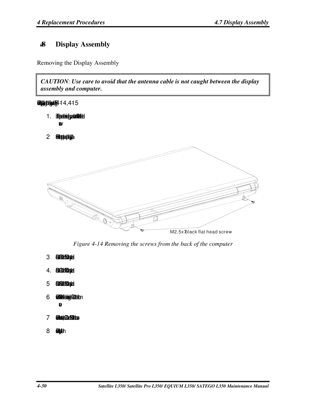
1.Turn the computer so the back is facing you and remove two M2.5x7 black flat head screws.
2.Restore the normal computer placement and open the display panel.
M2.5x7 black flat head screw
Figure 4-14 Removing the screws from the back of the computer
3.Disconnect the LCD/FL cable from CN5 on the system board.
4.Disconnect the CCD cable from CN7 on the system board.
5.Disconnect the MIC cable from CN3 on the system board.
6.Remove four M2.5x7 black flat head screws securing the LCD module to the bottom cover.
7.Remove the wireless antenna cables, CCD cable and MIC from the bottom cover.
8.Remove the display module.
Satellite L350/ Satellite Pro L350/ EQUIUM L350/ SATEGO L350 Maintenance Manual |