Back side
i.LINK (IEEE Connect an external device, such as a digital video cam- 1394) Port era to this port for
els are equipped with a i.LINK port. (Provided with some models)
NOTE: When multiple IEEE1394 devices are connected to a PC, the devices may not correctly be identified. This problem may occur when
Windows® XP is restarted while the devices are connected or when the power to the IEEE1394 devices is turned on before the PC is turned on. If it occurs, disconnect the IEEE1394 cables and then reconnect them.
Back side
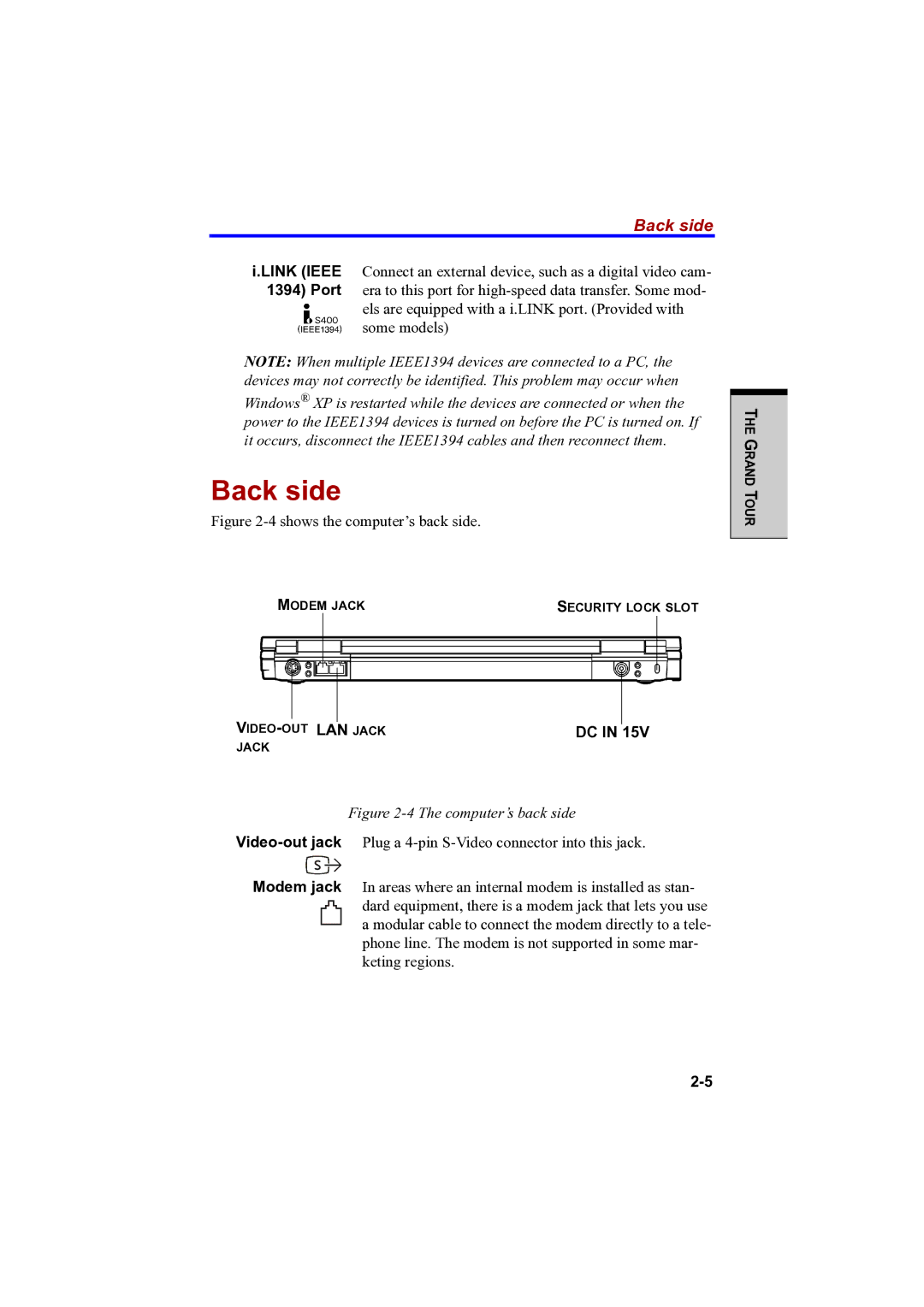
Figure 2-4 shows the computer’s back side.
THE GRAND TOUR
MODEM JACK | SECURITY LOCK SLOT |
|
|
|
|
|
|
|
|
|
|
|
|
DC IN | 15V | ||||
JACK |
|
| |||
Figure 2-4 The computer’s back side
Modem jack In areas where an internal modem is installed as stan- dard equipment, there is a modem jack that lets you use a modular cable to connect the modem directly to a tele- phone line. The modem is not supported in some mar- keting regions.