RAV-SM561AT-E, RAV-SM801AT-E, RAV-SM1101AT-E, RAV-SM1401AT-E
Contents
Installation Manual
Outdoor
To Disconnect the Appliance from Main Power Supply
Precautions for Safety
New Refrigerant Air Conditioner Installation
Refrigerant Piping
Accessory and Refrigerant
Accessory and Installation Parts
Selection of Installation
Before installation
Obstacle at rear side Upper side is free
Installation Place
Necessary Space for Installation
Obstacle at front side Upper side is free
Installation of Outdoor Unit
For Reference
Refrigerant Piping Connection
Optional Installation Parts Local Procure
Refrigerant Piping
Tightening of Connecting Part
Outer diam. of copper pipe Tightening torque
Vacuum pump
Evacuating
Air Purge
Valve size
Charge port
Tripping length power cord and connecting cable
How to remove the valve cover
How to wire
Electrical Work
Check and Test Operation
Final Installation Checks
Installation/Servicing Tools
Changes in the product and components
Applicable Control of Outdoor Unit
Recovery method of refrigerant
Work procedure
Night operation control Sound reduction
Connect the connecting cable correctly
Inappropriate grounding may cause electric shock
Connected to indoor/outdoor unit
Length of refrigerant pipe
Length of refrigerant pipe
Single unitIn installation
Or less
Knockout procedure
Knockout of Pipe Cover
Projection margin in flaring Unit mm
How to remove the front panel
Pipe Forming/End Positioning
Outer dia. of copper pipe R410A
Outer dia. of copper pipe Tightening torque
Evacuating
How to open the valve
Handle position
Stripping length power cord and connecting cable
Model RAV SM110 SM140 Power supply
Useful Functions
Self-Diagnosis by LED Indication
Outdoor unit cycle control Board
Applicable Control of Outdoor Unit
Contents
Indoor
Accessories Sold Separately
Page
Indoor unit
Outdoor unit
Display section
Operation section
Stop
Turn on the main power switch and/or the leakage breaker
Preparation
Push button
When restarting the operation after stop
Mode select button Mode
Temperature button
Start
How to stop swinging
How to set up the wind direction
How to start swinging
Heat operation
Timer operation
Cancel of timer operation
Get uniform circulation of room air
Never open doors and windows more often than necessary
Window curtains
If you do not plan to use the unit for more than 1 month
Cleaning of remote controller
Power supply to the air conditioner Thermo.-off operation
Checks before operation
Minutes protection function
Power failure
Heating characteristics Preheating operation
Warm air control In heating operation
Do not install the air conditioner in the following places
Be careful with noise or vibrations
Inoperative
Remote controller
RAV-SM561BT-E, RAV-SM801BT-E, RAV-SM1101BT-E, RAV-SM1401BT-E
Connecting duct
Test run display
Operation mode display
Fan mode display
Filter UP/DOWN button
Fan mode button Button
Unit and Auto flap button No function Operation lamp
Correct Usage
Automatic Operation Auto Changeover
Clear of timer operation
Do not open doors and windows more often than necessary
FAN only operation
AIR Conditioner Operations and Performance
RE-INSTALLATION
Air flow changes without FAN button set to Auto mode
Auto
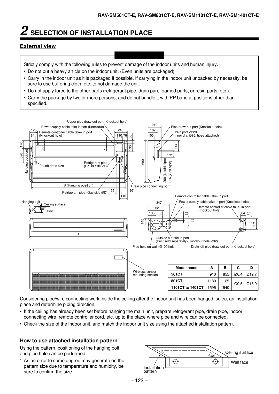
RAV-SM561CT-E, RAV-SM801CT-E, RAV-SM1101CT-E, RAV-SM1401CT-E
RAV-SM561CT-E, RAV-SM801CT-E, RAV-SM1101CT-E, RAV-SM1401CT-E
Air inlet Side and rear Air outlet Pipes and electric wires
Parts Name of Remote Controller
Operation section
Correct Usage
Automatic Operation Auto Changeover
Adjustment of Wind Direction
Timer Operation
Clean, please Gee, chilly Control
Maintenance
15 to 43C RAV-SP ∗∗∗
RE-INSTALLATION
Failures
These are not
100
Accessory parts and Parts to be procured locally
Accessory parts and Parts to be procured locally 117
105
Accessory parts and Parts to be procured locally
Separate sold parts
Precautions for Safety
Precautions for Safety
Avoid installing in the following places
Selection of Installation Place
Installation space
Model RAV SM560UT-E, SM800UT-E, SM1100UT-E
Height list of ceiling possible to be installed
Selection of installation place Discharge direction
Advice
Ceiling height
External view
SM800UT-E
Installation of hanging bolt
Installation of ceiling opening and hanging bolt
Installation of ceiling panel Sold separately
Installation of remote controller Sold separately
Flexible hose
Drain Piping Work
Piping/Heat insulating material
Adhesive inhibited
Check the draining
Connection procedure
Drain up
Perform heat insulating
Flaring diam. meter size a Unit mm
Refrigerant Piping and Evacuating
Permissible Piping Length and Heat
Tightening connection
Refrigerant amount to be added
Piping with outdoor unit
Open the valve fully
Gas leak check
Be sure to connect earth wire. Grounding work
Remote controller wiring
Cabling on the ceiling panel
Thermal insulation to cabling connecting port
Cable connection
Wiring diagram
Remote Controller Cabling
Cabling Cabling diagram
Test RUN
How to execute a test run
Case of wired remote controller
Before test run
Procedure Description
Troubleshooting
Confirmation of error history
Confirmation and check
Maintenance
Part name ’ty Shape Standard wired remote Controller
Part name ’ty Shape
Precautions for Safety
Precautions for Safety
Avoid installing in the following places
Installation space Selection of installation place
Secure the space required to installation and servicing
Installation of Indoor Unit
Installation procedure
Dimension
RAV-SM1101, 1401BT
Clamp mounting Removal of air filter
Mounting of clamp Accessory
Hanging down of indoor unit
Concealed duct type
Restriction to installation
Installation clearance
Ledge ceiling concealed duct type
Static pressure characteristics of each model
AIR Ducting Work
RAV-SM1101BT Round duct
Connecting method of the duct
Points at installation work
General cautions
Mounting of filter and canvas for suction port
Mounting of remote controller
Hanging of indoor unit
Thermal-insulating process
Piping material
Piping and cautions
Check of water drain
Drain-up
Connection of the drain hose
After electric piping work
Flaring dia meter size a Unit mm
Use copper pipe with 0.8 mm or more thickness
Refrigerant Piping and Evacuating
109
Cabling
111
112
Applicable Controls
Automatic address
To incorporate a filter sold separately
Setup of external static pressure
Exchange by wired remote controller
Short plug position CN112, CN111, CN110 from the left
Change of lighting time of filter sign
To secure better effect of heating
Clean the Return grilles with water
INSTALLATION/SERVICING Tools
Cleaning of Return grille
Cleaning of Air Filters
117
118
119
120
Case of wireless type
Height of ceiling
How to use attached installation pattern
Pipe knockout hole
Installation of hanging bolts
Knockout hole of power cable take-in port
Draw-out direction of pipe/cable
Installation of indoor unit
Collective piping
Case of taking pipe from the left side
Connection of drain hose Thermal insulating process
Connection of drain pipe
127
128
129
130
131
132
133
134
Case of installation to high ceiling
When using wireless remote controller
136
Removal of suction grille
Tools
Cleaning of air filter