April
Blower Coil Air Handler
Refrigerant warning information
Environmental Concerns
Responsible Refrigerant Practices
Hazard of Explosion and Deadly Gases
Trademarks
About This Manual
Table of Contents
BCXC-SVX01B-EN
Digits 1, 2, 3, 4 Unit Model
Digit 16 Motor Horsepower
Digits 5, 6, 7 Unit Size
Digit 8 Unit Voltage
Model Number Description
Blower Coil General Information
General Information
General Information
Pre-Installation
Receiving and Handling
Jobsite Storage Recommendations
Service Access
Installation Preparation
Pre-Installation
Unit size Dimension a
Rigging and Handling
Unit Handling Procedure
Improper Unit Lift
Unit Location Recommendations
Skid Removal
Pre-Installation Checklist
Horizontal blower coil dimensions in. and weights lb
Dimensions and Weights
Unit Size RH LH Weight
Horizontal Blower Coil
Vertical blower coil dimensions in. and weights lb
Dimensions and Weights
Unit Size Weight
Vertical Blower Coil
Angle filter and mixing box dimensions in. and weights lb
Angle Filter and Mixing Box
Unit size
AIR Flow Filter Filter Access Panel
Bottom or Top Access Filter Box
Electric Heat
Electric heat dimensions in. and weights lb
Steam Coil
Steam coil box dimensions in. and weights lb
Coil Connections, NPT
Supply Return
Hydronic coil connection sizes, OD
Coil Connections
DX coil connection sizes, OD
Steam coil connection sizes, female connection, NPT
Basic Piping
Piping Packages
Dimensions and Weights Deluxe Piping
Actual size
Piping Nominal
Installing Wall Mounted Controls
Installation Controls
Zone Sensor Installation
Wiring Instructions
Installation Controls
Communication Wiring
Service Communication Wiring
Zone Sensors Without Interconnecting Wiring
Tracer Summit Communication Wiring
Installation Electrical
Zone sensor maximum wiring distances, ft m
Installation Electrical
Wire size range Max. wiring distance
Electrical Grounding Restrictions Hazardous Voltage
Useful Formulas
Available electric heat, min-max kW
Unit size Voltage
Motor electrical data
240/50/1
220/50/1
190/50/3
380/50/3
Installing the Unit
Installation Mechanical
Bchc Installation Procedure
Horizontal Units, Model Bchc
Vertical Units, Model Bcvc
Installation Mechanical
Mixing Box Option
Heating Coil Option
Mixing Box Installation Procedure
Linkage Installation Procedure
Condensate Drain Connections
Duct Connections
Recommended drain trap installation for draw-through units
Water Coil Connections
Installation Piping
Potential coil-freeze condition
Refrigerant Coil Piping
Installation Piping
Valve Damage
Suction Line
Field-installed evaporation piping example
Field-Installing Evaporator Piping
Coil Condensate
Steam Piping
General
Steam Coils
Type NS steam coils, horizontal tubes for horizontal airflow
Controls Interface
Control Options
Tracer Controllers
Controls Interface
Rover Service Software
Tracer controller input/output summary
Tracer controller ZN010 ZN510 ZN520
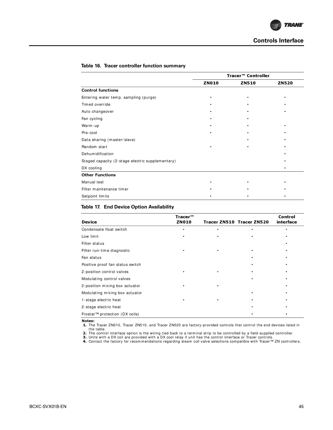
Tracer controller function summary
End Device Option Availability
Tracer Control Device ZN010 Tracer ZN510 Tracer ZN520
Pre-Start
Pre-Start Checklist
Receiving
Unit Location
Ductwork
Pre-Start Component Overview
Unit Piping
Electrical
Start-Up
Sequence of Operation
Tracer ZN Controller Sequence of Operation
Unoccupied Mode
Occupied Mode
Sensor type Sensor position Unit occupancy mode
Start-Up
Occupied Standby Mode Tracer ZN510 or ZN520 only
Cooling Operation
Occupied Bypass Mode, Tracer ZN510 or ZN520 Only
DX Cooling Tracer ZN520 only
Start-Up Economizer Cooling Tracer ZN520 Only
Discharge Air Tempering Tracer ZN520 Only
Heating Operation
Tracer ZN520 fan configuration
Fan Mode Operation Rotating Components
Auto fan operation Fan speed default
Fan sequence of operation
Tracer ZN010 and ZN510
Fan Speed Switch
Tracer ZN520
Continuous Fan Operation
Fan mode operation, Tracer ZN010 and ZN510
Fan Off Delay
Start-Up Fan Cycling Operation
Fan Start on High Speed
Local fan switch enabled
Entering Water Temperature Sampling Function
Two- and Four-Pipe Changeover Operation
Fan operation in heating and cooling modes
Unit type EWT sensor required? Coil water temperature
Unit mode as related to water temperature
Electric Heat Operation
Economizer Damper Tracer ZN520 Only
Tracer Dehumidification Tracer ZN520 Only
BIP1 Low Temperature Detection Option
Data Sharing Tracer ZN510 or ZN520 Only
Binary Inputs
BIP2 Condensate Overflow Detection Option
Binary input configurations
BIP3 Occupancy Sensor
BIP4 Fan Status ZN520 Only
Binary Outputs
Analog Inputs
Analog inputs
Analog input Terminal Function Range ZN010 ZN510 ZN520
Binary output configuration
Space Temperature Measurement
Zone sensor wiring connections
Zone Sensor
External Setpoint Adjustment
Fan Mode Switch
Fan Switch
Local Setpoint
Communication Jack
On/Cancel Buttons
Maintenance Procedures
Maintenance
Fan Assembly Set Screws
Maintenance
Fan Belt Tension
Torque in.-lb Ft-lb
BCBH/BCVC valve package waterflow limits
Belt tension
BCHC/BCVC coil general data
Hydronic coil data
Row coil
Steam coil data
Drive data
Unit Motor Motor sheave Fan sheave Belt
1750 1450 Size Watts Browning Trane 60 Hz 50 Hz
Potential unit damage from coil cleaners
Coil Maintenance
Inspecting and Cleaning Coils
Steam, Hot Water, and Cooling Coil Cleaning Procedure
Rotating parts
Periodic Maintenance Checklists
Maintenance
Diagnostics
Troubleshooting
LED Activity
Diagnostics
Manual Output Test Procedure
Manual Output Test
Translating Multiple Diagnostics
Diagnostics
Tracer ZN520 test sequence
Fan Cool output a Heat output Damper Steps J1-1, J1-3
Automatic Reset by the Controller
Resetting Diagnostics
Cycling Power
Diagnostics Manual Output Test
Rover Service Tool
Diagnostic Reset Tracer ZN510 or ZN520 Only
Tracer ZN520 diagnostics
Tracer ZN010 and ZN510 controller diagnostics
Diagnostic Latching Fan Valves Electric heat Damper
Diagnostic Fan Other outputsa
Fan outputs do not energize
Common Diagnostics
Valves stay closed
Probably cause Explanation
Valves stay open
Electric heat not operating
Fresh air damper stays closed
DX or electric outputs do not energize
Fresh air damper stays open
Two-Pipe Bcxc with Tracer ZN510
Wiring Diagrams
Four-Pipe Bcxc with Tracer ZN510
Wiring Diagrams
Four-Pipe Bcxc with Tracer ZN510
Two-Pipe Bcxc with Tracer ZN520
Four-Pipe Bcxc with Tracer ZN520
Four-Pipe Bcxc with Tracer ZN520
Four-Pipe Bcxc with Tracer ZN520
Four-Pipe Bcxc with Control Interface
Four-Pipe Bcxc with Control Interface
Bcxc with DX Coil and Tracer ZN520
Field Installed Device
Bcxc with DX Coil, Hydronic Heating, and Tracer ZN520
BCXC-SVX01B-EN

