5.Installation (continued)
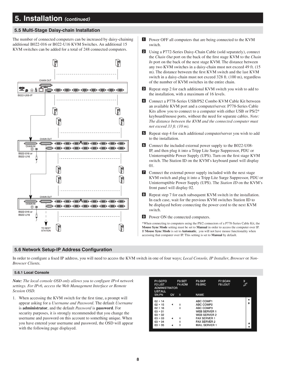
5.5Multi-Stage Daisy-chain Installation
The number of connected computers can be increased by
5.6 Network Setup-IP Address Configuration
Power OFF all computers that are being connected to the KVM switch.
Using a
Repeat step 2 for each additional KVM switch you wish to add to the installation, with a maximum of 16 levels.
Connect a
Repeat step 4 for each additional computer/server you wish to add to the installation.
Connect the included external power supply to the
Connect the external power supply included with the next stage KVM switch and plug it into a Tripp Lite Surge Suppressor, PDU or Uninterruptible Power Supply (UPS). The Station ID on the KVM’s front panel will display 02.
Repeat step 7 for each subsequent KVM switch in the installation. In each case, wait for the previous KVM switches Station ID to be displayed before connecting the power cord to the next KVM switch.
Power ON the connected computers.
*When connecting to computers using the PS/2 connectors of a
In order to configure a fixed IP address, you will need to access the KVM switch in one of four ways; Local Console, IP Installer, Browser or Non- Browser Clients.
5.6.1 Local Console
Note: The local console OSD only allows you to configure IPv4 network settings. For IPv6, access the Web Management Interface or Remote Session OSD.
1.When accessing the KVM switch for the first time, a prompt will appear asking for a Username and Password. The default Username is administrator, and the default Password is password. For security purposes, it is strongly recommended that you change the username and password on this account to something unique. When you have entered your username and password, the OSD will appear with the following page displayed.
8