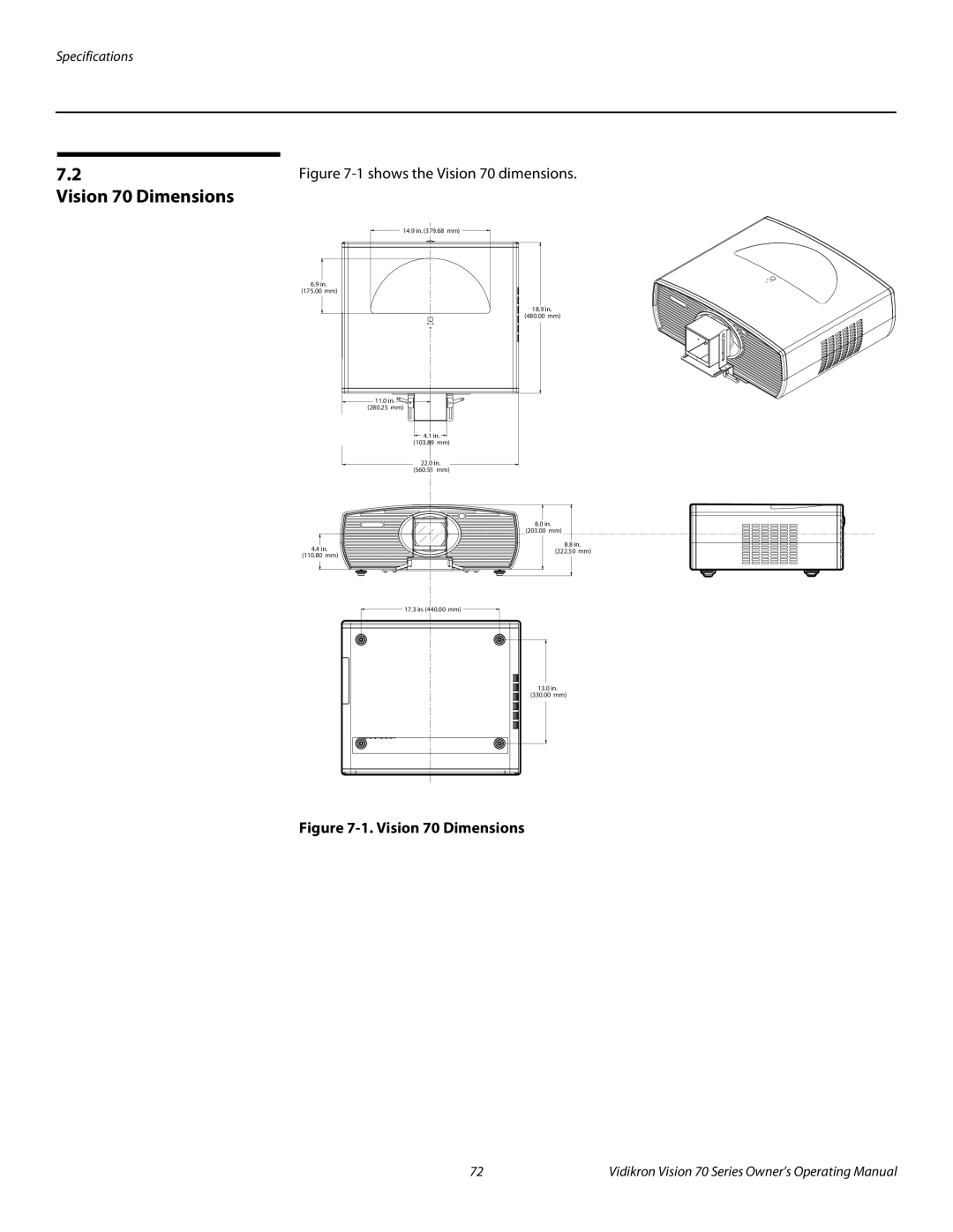
SERIES 1080p DLP PROJECTORS
O W N E R ’ S O P E R A T I N G M A N U A L
Vision Vision 70/CineWide Vision 70/CineWide with AutoScope
Page
TWO YEAR LIMITED WARRANTY
WHAT IS COVERED UNDER THE TERMS OF THIS LIMITED WARRANTY
WHAT IS NOT COVERED UNDER THE TERMS OF THIS LIMITED WARRANTY
For Projectors, Video Processors and Controllers
EFFECTIVE WARRANTY DATE
IMPORTANT -- WARRANTY REGISTRATION
CONTACT A VIDIKRON AUTHORIZED SERVICE CENTER TO OBTAIN SERVICE
COPYRIGHT AND TRADEMARKS
ADDITIONAL INFORMATION
VIDIKRON Attn Customer Service Department 2900 Faber Street
VIDIKRON PRODUCT INFORMATION RETAIN THIS INFORMATION FOR YOUR RECORDS
Union City, CA Ph 510 Fax 510 Toll Free 888 4VIDIKRON
Safety Precautions
1Table of Contents
Description, Features and Benefits
Vision 70 Connector Panel
Installation Considerations
Table of Contents
Maintenance and Troubleshooting
Operation
viii
Table of Contents
Specifications
Vidikron Vision 70 Series Owner’s Operating Manual
Serial Communications
Table of Contents
Vidikron Vision 70 Series Owner’s Operating Manual
1List of Figures
Vidikron Vision 70 Series Owner’s Operating Manual
List of Figures
Vidikron Vision 70 Series Owner’s Operating Manual
A carriage return must be used after each command or string
1Introduction
About This Manual
1.2 Using This Manual
DANGER appears when a given action can cause severe injury or death
DANGER
NOTES emphasize text with unusual importance or special significance
1.3 Description, Features and Benefits
Note screen
Optional Accessories
2. Controls and Functions
Vision 70 at a Glance
Figure 2-1. Vision 70 Front/Side/Top View 1. VIDIKRON LOGO
2. TOP IR SENSOR 3. LAMP LED
5. TEMP LED
6. INTAKE VENT 7. EXHAUST VENT 8. FRONT IR SENSOR 9. PROJECTION LENS
Figure 2-2. Vision 70 Rear/Bottom/Side View
Controls and Functions
2.2 Vision 70 Connector Panel
5. FRONT/REAR ADJUSTERS
Figure 2-3. Vision 70 Connector Panel
2. DOOR RELEASE BUTTON 3. CABLE OPENING
3. COMP 1 RCA connectors
For best results, do not run your DVD player in progressive mode
2.3 Built-In Keypad
1. HDMI Digital
2.4 Vision 70 Remote Control
Figure 2-4. Vision 70 Remote Control
Controls and Functions
Vidikron Vision 70 Series Owner’s Operating Manual
1. ON / OFF
2. Source Selection Buttons COMP 1 SD Component
S-VID S-Video
VIDEO
4. Memory Preset Buttons MEM1
ISF NT
ISF DAY
5. Cursor Keys
Remote Control/Built-In Keypad Functional Comparison
Figure 2-5. Remote Control/Built-In Keypad Functional Cross-Reference
9. Motorized Lens Controls LENS SHIFT
FOCUS
3Installation
3.1 Remote Control
3.2 Quick Setup
Table 3-1. Installation Overview
Note specialist
Installation
3.3 Installation Considerations
Table 3-2. Projector Installation Options
Table 3-3. Throw Ratios for the Vision 70 Series
Figure 3-1. Estimating Throw Distance
Ceiling Installation
Floor Installation
Figure 3-2. Projector Placement
Figure 3-3. Vertical Lens Shift EXAMPLE ONLY
Figure 3-4. Folded Optics
Screen Mirror
Installing the Optional CineWide Lens Mount
install the projector and adjust the primary lens
Attaching the AutoScope Lens Motor or Fixed CineWide Base Plate to
Projector
Installation
Vidikron Vision 70 Series Owner’s Operating Manual
Figure 3-6. Vision 70 With Ceiling Mount Extension Brackets
Ceiling Mount Extension Brackets
ceiling mounting plate
plate
Plate - Bottom View
particularly important when ceiling-mounting a Vision 70/CineWide
3.5 Mounting the Vision
Use only the Vidikron-approved ceiling mount kit designed for your
with it
3.6 Connections to the Vision
Use the HDMI input whenever possible. This ensures the highest video
Figure 3-8. HDMI/DVI Source Connections
The Vision 70 supports computer resolutions of 1024x768, 800x600 and
Figure 3-9. RGB Connections
Figure 3-10. Progressive Component Video Connections
Installation
Y Pb Pr
Vidikron Vision 70 Series Owner’s Operating Manual
DTV Source DVD Player, VCR Satellite Receiver etc
Figure 3-11. Composite, S-Video and Component Video Connections
Installation
Vidikron Vision 70 Series Owner’s Operating Manual
Figure 3-12. RS-232 Control System Connection
Installation
DTV Source DVD Player, VCR Satellite Receiver etc
RS-232 Controller
Figure 3-14. Connecting the 12-Volt Trigger Output to Other Equipment
Connecting 12-Volt Trigger Output to External Theater Equipment
3.7 Turning on the Power
The input voltage to the AutoScope lens motor must be between 100 and
3.8 Changing the OSD Language 3.9 Adjusting the Picture Orientation
3.10 Primary Lens Adjustments
Focus Zoom Vertical Lens Shift
3.11 Installing and Adjusting the CineWide Anamorphic Lens
Figure 3-15. Standard Vision 70 Anamorphic Lens Mounting Assembly
Adjusting the Lens Height Y
Correct Lens Angle Incorrect Lens Angle
Figure 3-16. Anamorphic Lens Mounting Assembly - Exploded View
and Adjustment
Vision 70/CineWide with
AutoScope
Attach Lens Mounting Assembly to Lens Motor Carriage Plate
Figure 3-17. Attaching the Anamorphic Lens to the Lens Adapter Ring
Adjusting the Horizontal X Lens Position
Too Far Left Correct position Too Far Right
Height/Y Adjustment T-Screws on either side of the lens. Then, slowly move the anamorphic lens into place so that there are no shadows on the top or bottom of the screen
Anamorphic Lens Top View
Installation
Vidikron Vision 70 Series Owner’s Operating Manual
Adjusting the Geometry
Using Picture-In-Picture/ Picture-By-Picture PIP/PBP
4Operation
4.1 Selecting Video Memory
4.2 Selecting an Aspect Ratio 4.3 Selecting An Input Source 4.4
4.5 Using the On-Screen Menus
Adjust
Installation
Service
Picture
Picture Adjust
Main Menu
Perform the adjustments in the order listed here
Figure 4-2. Typical PLUGE Pattern for Adjusting Brightness
Figure 4-3. Typical Gray Bar Pattern for Adjusting Contrast
gray
yellow
cyan
gray
yellow
cyan
green
Figure 4-5. Typical Test Pattern for Adjusting Sharpness
The Sharpness setting has no effect if the Video Filter described on
You must enter a passcode in order to enter the Service menu
When you change the aspect ratio, save the change to a preset
Image Option
Operation
Table 4-1. Aspect Ratio Settings
Operation
Description
Table 4-1. Aspect Ratio Settings continued
lens then restores the proper
Cinema
CINEMA
To adjust the image position with a 480i source, use the Image Shift
Projector Status
Vidikron recommends that the keystone feature not be used unless
EXIT to return to the previous menu or MENU to exit
Installation
Service
White Balance Gamma Selection ICC Adjust Image Over Scan
Horizontal Masking Fan Control Lamp Reset Timer RS-232 Baud Rate
Remote Control Screen Trigger Mode Return to User OSD
For each component color, you can adjust the following
Page
You can change the secondary IR code if either
When you change a setting, save the change to a preset afterwards
This menu should be used by ISF-certified technicians only
ISF Calibration
Splash Screen Timer Use the or button to set the Splash Screen Timer. This timer controls how long the startup ISF and Vidikron logo image stays on-screen after you turn on the projector. Select from 5 to 60 seconds, in one-second increments. When finished, press EXIT
Operation
Vidikron Vision 70 Series Owner’s Operating Manual
5Maintenance and Troubleshooting
5.1 Lamp Replacement
lamp assembly for replacement
5.2 Troubleshooting Tips
Table 5-1. Troubleshooting Chart
Maintenance and Troubleshooting
Table 5-1. Troubleshooting Chart continued
Maintenance and Troubleshooting
Vidikron Vision 70 Series Owner’s Operating Manual
source are connected to the
Maintenance and Troubleshooting
Vidikron Vision 70 Series Owner’s Operating Manual
6.2 Serial Command Syntax
RS-232 Connection and Port Configuration
Table 6-1. Serial Commands
6Serial Communications
Table 6-1. Serial Commands continued
Serial Communications
Table 6-1. Serial Commands continued
Serial Communications
x081x
Vidikron Vision 70 Series Owner’s Operating Manual
Table 6-1. Serial Commands continued
Serial Communications
x282x
7Specifications
Table 7-1. Vision 70 Specifications
Vision 70 Specifications
Vidikron Vision 70 Series Owner’s Operating Manual
Table 7-1. Vision 70 Specifications continued
Specifications
Table 7-1. Vision 70 Specifications continued
Specifications
Limited Warranty
Specifications are subject to change without notice
7.2 Vision 70 Dimensions
Figure 7-1. Vision 70 Dimensions
Specifications
Vidikron Vision 70 Series Owner’s Operating Manual
Appendix A. Personalizing the ISF Splash Screen on the Vision
Note procedure
Only ISF-trained and -certified technicians should attempt this
9. Power-cycle the projector to see the change
Personalizing the ISF Splash Screen on the Vision
CALIBRATED FOR John Doe By Tinh Ho CUSTOM BUILT BY
Vidikron Vision 70 Series Owner’s Operating Manual
Page
Vidikron
2900 Faber Street Union City, CA 94587
SERIAL NUMBER