VFR-400 • 5403548 • REV D • 10/07

PROGRAM #9

For One Sprinkler System

Viking Sprinkler

1 Release Zone

1. FIRECYCLE III Wet Multicycle System


System Types

and Manual


Release Zone


ZONES (Initiating Circuits)


OUTPUTS

SUP 1

SUP 2


#1

#2


#3

#4

(Indicating Circuits)


Supervisory Zone

Valve Tamper


FIRECYCLE

Supervisory


Waterflow

Manual


Supervisory Zone


Detector Zone

Zone


Zone

Release Zone

#1 General Alarm


X


X

X


#2 Supervisory Bell

X

X


X


#3 Release Solenoid


X


X

#4 N/O Solenoid


X


X


OPERATION DESCRIPTION


Inputs:

1 FIRECYCLE Detection zone, 1 Supervisory zone, 1 Waterflow zone, 1 Manual Release zone, 2


Supervisory zones


Outputs:

1 General Alarm, 1 Supervisory Bell, 1 Release Solenoid, and 1 N/O Solenoid


Operation:

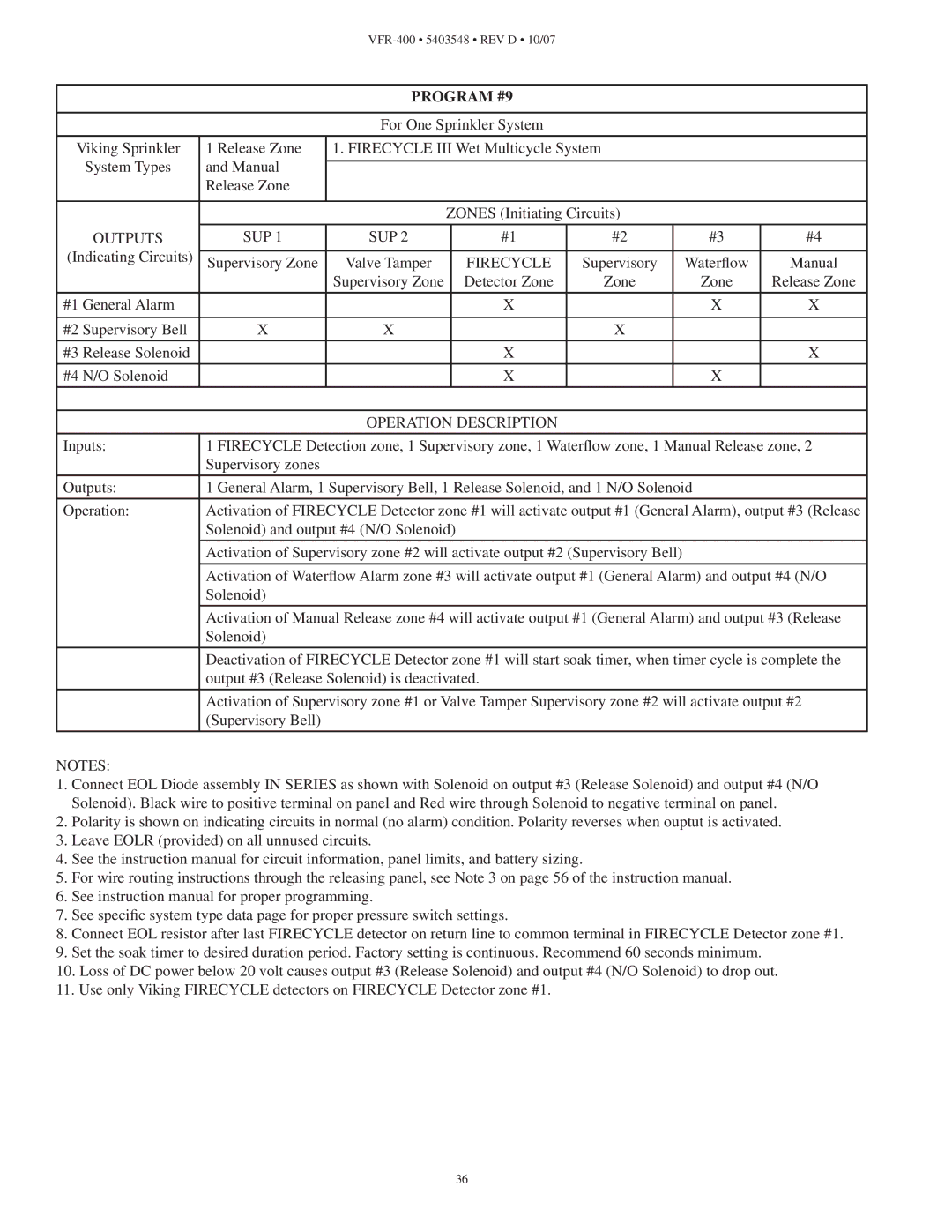
Activation of FIRECYCLE Detector zone #1 will activate output #1 (General Alarm), output #3 (Release


Solenoid) and output #4 (N/O Solenoid)


Activation of Supervisory zone #2 will activate output #2 (Supervisory Bell)


Activation of Waterflow Alarm zone #3 will activate output #1 (General Alarm) and output #4 (N/O


Solenoid)


Activation of Manual Release zone #4 will activate output #1 (General Alarm) and output #3 (Release


Solenoid)


Deactivation of FIRECYCLE Detector zone #1 will start soak timer, when timer cycle is complete the


output #3 (Release Solenoid) is deactivated.


Activation of Supervisory zone #1 or Valve Tamper Supervisory zone #2 will activate output #2


(Supervisory Bell)


NOTES:

1.Connect EOL Diode assembly IN SERIES as shown with Solenoid on output #3 (Release Solenoid) and output #4 (N/O Solenoid). Black wire to positive terminal on panel and Red wire through Solenoid to negative terminal on panel.

2.Polarity is shown on indicating circuits in normal (no alarm) condition. Polarity reverses when ouptut is activated.

3.Leave EOLR (provided) on all unnused circuits.

4.See the instruction manual for circuit information, panel limits, and battery sizing.

5.For wire routing instructions through the releasing panel, see Note 3 on page 56 of the instruction manual.

6.See instruction manual for proper programming.

7.See specific system type data page for proper pressure switch settings.

8.Connect EOL resistor after last FIRECYCLE detector on return line to common terminal in FIRECYCLE Detector zone #1.

9.Set the soak timer to desired duration period. Factory setting is continuous. Recommend 60 seconds minimum.

10.Loss of DC power below 20 volt causes output #3 (Release Solenoid) and output #4 (N/O Solenoid) to drop out.

11.Use only Viking FIRECYCLE detectors on FIRECYCLE Detector zone #1.

36

Page 36
Image 36
Viking VFR-400 instruction manual Program #9

VFR-400 specifications

The Viking VFR-400 is a light sport aircraft that has garnered attention for its innovative design and advanced technology. This aircraft is known for its versatility, performance, and safety features, making it a suitable choice for both recreational flying and pilot training.

One of the standout features of the VFR-400 is its efficient aircraft structure. Constructed primarily of high-strength composite materials, the VFR-400 boasts a lightweight yet durable frame. This not only enhances its aerodynamics but also contributes to increased fuel efficiency. The aircraft is powered by a reliable Rotax engine, which is well-regarded in the aviation community for its exceptional performance and low operational costs.

The VFR-400 is equipped with a low-wing design, which is optimized for stability and maneuverability. Pilots appreciate the responsive handling characteristics, which make it an enjoyable aircraft to fly, whether on short excursions or longer journeys. The spacious cabin design offers ample room for two occupants, ensuring comfort during flights. Large cockpit glass provides excellent visibility during takeoff and landing, critical times when situational awareness is paramount.

In terms of avionics, the VFR-400 features advanced electronic systems, including a modern glass cockpit display. This integration of technology provides pilots with real-time flight data, ensuring better navigation and situational awareness. Moreover, the aircraft often comes equipped with autopilot features, enhancing the flying experience, especially on longer flights.

Safety is a key aspect of the VFR-400 design. It incorporates redundant control systems, advanced braking systems, and robust structural integrity to withstand various in-flight scenarios. The landing gear is designed for easy maintenance and reliability, allowing for smooth landings on various surface types.

The VFR-400 is designed with fuel efficiency in mind, allowing for longer flight durations while keeping operational costs low. Its impressive range and payload capacity make it a highly flexible option for different mission profiles, from pilot training to leisurely flights.

Overall, the Viking VFR-400 exemplifies the spirit of modern aviation with its combination of performance, safety, and comfort. It stands out in the light sport aircraft category for its thoughtful engineering and commitment to delivering a quality flying experience. Whether for a seasoned aviator or someone new to flying, the VFR-400 offers a compelling platform for exploration and adventure in the skies.