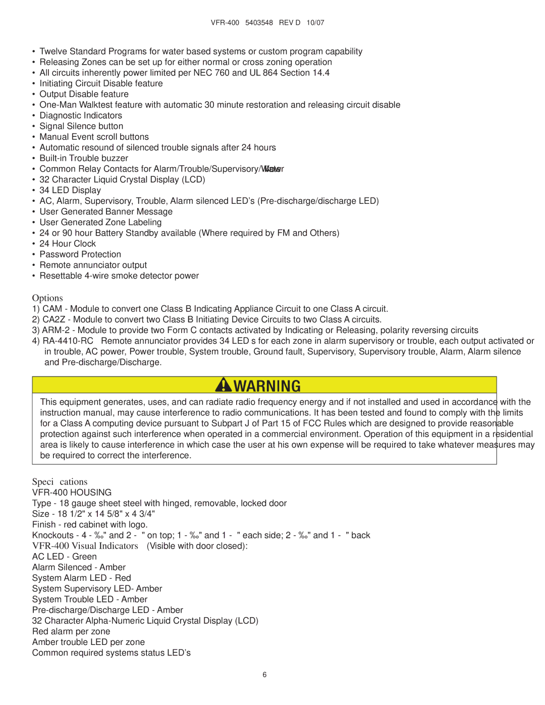
VFR-400 specifications
The Viking VFR-400 is a light sport aircraft that has garnered attention for its innovative design and advanced technology. This aircraft is known for its versatility, performance, and safety features, making it a suitable choice for both recreational flying and pilot training.One of the standout features of the VFR-400 is its efficient aircraft structure. Constructed primarily of high-strength composite materials, the VFR-400 boasts a lightweight yet durable frame. This not only enhances its aerodynamics but also contributes to increased fuel efficiency. The aircraft is powered by a reliable Rotax engine, which is well-regarded in the aviation community for its exceptional performance and low operational costs.
The VFR-400 is equipped with a low-wing design, which is optimized for stability and maneuverability. Pilots appreciate the responsive handling characteristics, which make it an enjoyable aircraft to fly, whether on short excursions or longer journeys. The spacious cabin design offers ample room for two occupants, ensuring comfort during flights. Large cockpit glass provides excellent visibility during takeoff and landing, critical times when situational awareness is paramount.
In terms of avionics, the VFR-400 features advanced electronic systems, including a modern glass cockpit display. This integration of technology provides pilots with real-time flight data, ensuring better navigation and situational awareness. Moreover, the aircraft often comes equipped with autopilot features, enhancing the flying experience, especially on longer flights.
Safety is a key aspect of the VFR-400 design. It incorporates redundant control systems, advanced braking systems, and robust structural integrity to withstand various in-flight scenarios. The landing gear is designed for easy maintenance and reliability, allowing for smooth landings on various surface types.
The VFR-400 is designed with fuel efficiency in mind, allowing for longer flight durations while keeping operational costs low. Its impressive range and payload capacity make it a highly flexible option for different mission profiles, from pilot training to leisurely flights.
Overall, the Viking VFR-400 exemplifies the spirit of modern aviation with its combination of performance, safety, and comfort. It stands out in the light sport aircraft category for its thoughtful engineering and commitment to delivering a quality flying experience. Whether for a seasoned aviator or someone new to flying, the VFR-400 offers a compelling platform for exploration and adventure in the skies.

