3
o:white/orange stripe O: orange solid
g:white/green stripe B: blue solid
b:white/blue stripe G: green solid
br: white/brown stripe
BR: brown solid
VIVOTEK
3� You will need an RJ45 crimping tool to
attach the Ethernet wires to a connec-
tor� When done, connect the cable to the camera’s Ethernet RJ45 socket �
| o |
|
| 1 |
|
| O |
|
| 2 |
|
| g |
|
| 3 |
|
| B |
|
| 4 |
|
|
|
|
| ||
| b |
|
| 5 |
|
| G |
|
| 6 |
|
| br |
|
| 7 |
|
| BR |
|
| 8 |
|
|
|
|
| ||
| |||||
|
|
| |||
|
|
|
|
|
|
4� Press the Ethernet cable into the routing path | 4 | |
at the bottom of the camera so that the cable | ||
| ||
will not get in the way when the metal mounting |
| |
plate is attached� |
|
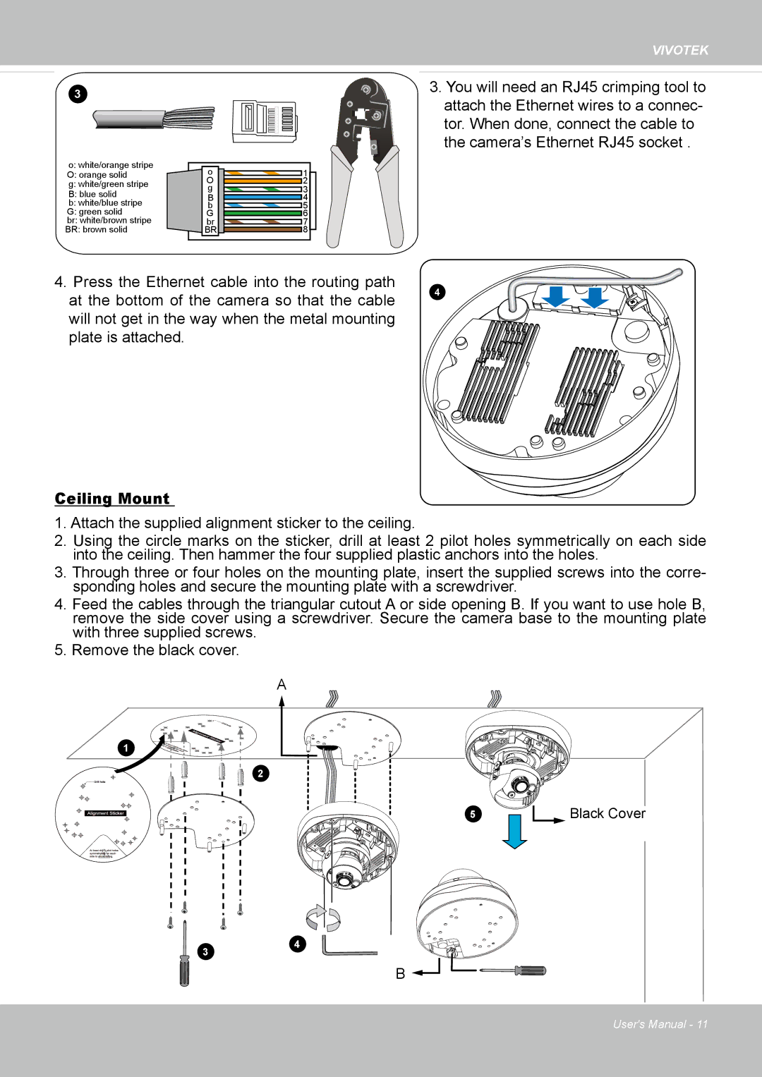
Ceiling Mount
1� Attach the supplied alignment sticker to the ceiling�
2� Using the circle marks on the sticker, drill at least 2 pilot holes symmetrically on each side into the ceiling� Then hammer the four supplied plastic anchors into the holes�
3� Through three or four holes on the mounting plate, insert the supplied screws into the corre- sponding holes and secure the mounting plate with a screwdriver�
4� Feed the cables through the triangular cutout A or side opening B� If you want to use hole B, remove the side cover using a screwdriver� Secure the camera base to the mounting plate with three supplied screws�
5� Remove the black cover�
A
1
2
5
Black Cover
34
B ![]()
![]()
![]()
![]()
![]()
User's Manual - 11