VIVOTEK
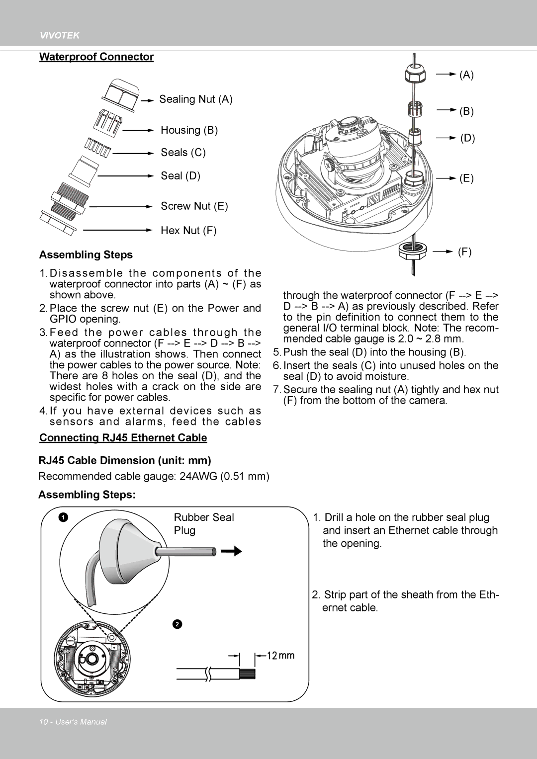
Waterproof Connector
![]()
![]()
![]()
![]()
![]()
![]()
![]() Sealing Nut (A)
Sealing Nut (A)
Housing (B)
Seals (C)
Seal (D)
Screw Nut (E)
Hex Nut (F)
Assembling Steps
1� Disassemble the components of the waterproof connector into parts (A) ~ (F) as shown above�
2� Place the screw nut (E) on the Power and GPIO opening�
3� Feed the power cables through the waterproof connector (F
4� If you have external devices such as sensors and alarms, feed the cables
Connecting RJ45 Ethernet Cable
RJ45 Cable Dimension (unit: mm)
Recommended cable gauge: 24AWG (0�51 mm)
![]() (A)
(A)
![]() (B)
(B)
![]() (D)
(D)
![]()
![]()
![]()
![]()
![]()
![]()
![]()
![]()
![]()
![]()
![]()
![]()
![]()
![]()
![]()
![]()
![]()
![]()
![]()
![]()
![]()
![]()
![]()
![]()
![]()
![]()
![]()
![]()
![]()
![]()
![]()
![]()
![]() (E)
(E)
![]()
![]() (F)
(F)
through the waterproof connector (F
5� Push the seal (D) into the housing (B)�
6� Insert the seals (C) into unused holes on the seal (D) to avoid moisture�
7� Secure the sealing nut (A) tightly and hex nut
(F) from the bottom of the camera�
Assembling Steps: |
|
|
1 | Rubber Seal | 1� Drill a hole on the rubber seal plug |
| Plug | and insert an Ethernet cable through |
|
| the opening� |
2� Strip part of the sheath from the Eth- ernet cable�
2
10 - User's Manual