VXI Technology, Inc.
|
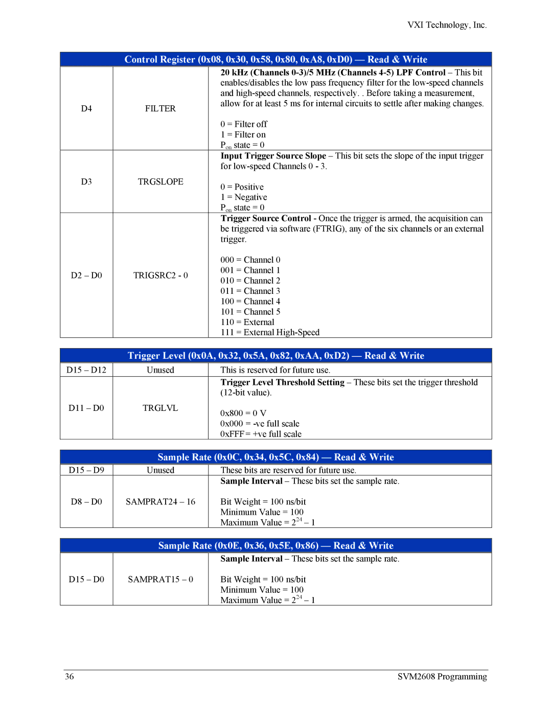
| Control Register (0x08, 0x30, 0x58, 0x80, 0xA8, 0xD0) — Read & Write | ||
|
|
| 20 kHz (Channels | |
|
|
| enables/disables the low pass frequency filter for the | |
|
|
| and | |
| D4 | FILTER | allow for at least 5 ms for internal circuits to settle after making changes. | |
|
|
| ||
|
|
| 0 = Filter off | |
|
|
| 1 = Filter on | |
|
|
| Pon state = 0 | |
|
|
| Input Trigger Source Slope – This bit sets the slope of the input trigger | |
|
|
| for | |
| D3 | TRGSLOPE | 0 = Positive | |
|
|
| ||
|
|
| 1 = Negative | |
|
|
| Pon state = 0 | |
|
|
| Trigger Source Control - Once the trigger is armed, the acquisition can | |
|
|
| be triggered via software (FTRIG), any of the six channels or an external | |
|
|
| trigger. | |
|
|
| 000 | = Channel 0 |
| D2 – D0 | TRIGSRC2 - 0 | 001 | = Channel 1 |
| 010 | = Channel 2 | ||
|
|
| ||
|
|
| 011 | = Channel 3 |
|
|
| 100 | = Channel 4 |
|
|
| 101 | = Channel 5 |
|
|
| 110 | = External |
|
|
| 111 | = External |
Trigger Level (0x0A, 0x32, 0x5A, 0x82, 0xAA, 0xD2) — Read & Write
D15 – D12 | Unused | This is reserved for future use. | |
|
| Trigger Level Threshold Setting – These bits set the trigger threshold | |
|
| ||
D11 – D0 | TRGLVL | 0x800 | = 0 V |
|
| ||
|
| 0x000 | = |
|
| 0xFFF | = +ve full scale |
Sample Rate (0x0C, 0x34, 0x5C, 0x84) — Read & Write
D15 – D9 | Unused | These bits are reserved for future use. |
|
| Sample Interval – These bits set the sample rate. |
D8 – D0 | SAMPRAT24 – 16 | Bit Weight = 100 ns/bit |
|
| Minimum Value = 100 |
|
| Maximum Value = 224 – 1 |
Sample Rate (0x0E, 0x36, 0x5E, 0x86) — Read & Write
D15 – D0
SAMPRAT15 – 0
Sample Interval – These bits set the sample rate.
Bit Weight = 100 ns/bit
Minimum Value = 100
Maximum Value = 224 – 1
36 | SVM2608 Programming |
