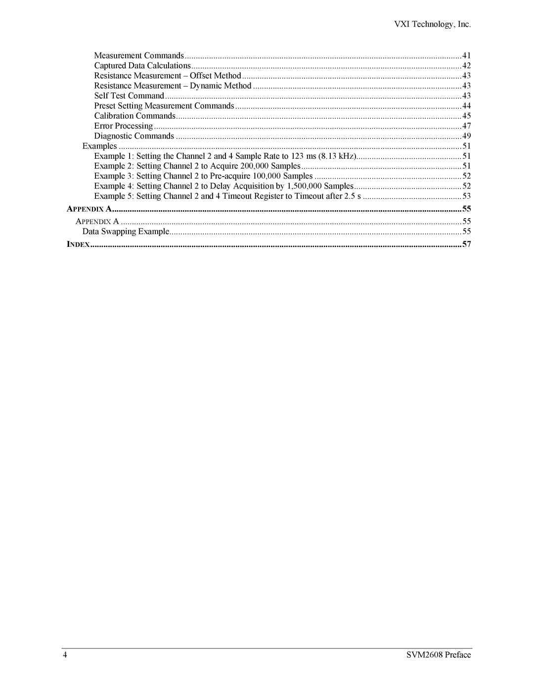
Contents
SVM2608
VXI Technology, Inc
Table of Contents
Self Test Command
Warranty
Limitation of Warranty
Certification
Restricted Rights Legend
EMC
Steve Mauga, QA Manager
Service should only be performed by qualified personnel
Terms and Symbols
Use Proper Power Cord
Use Proper Power Source
Avoid Electric Shock
Ground the Product
Operating Conditions
Improper Use
VXI Technology World Headquarters
VXI Technology Cleveland Instrument Division
VXI Technology Lake Stevens Instrument Division
Technical Support
VXI Technology, Inc SVM2608 Preface
Introduction
Overview
Scale
Acquiring Data
Triggering
Delayed Trigger
Linear Mode
Pre-Trigger
Fifo Mode
Commands
Calibrations
Test Bus
Option
SVM2608 Block Diagram
SVM2608 Environmental Specifications
Physical Description
Front Panel Interface Wiring
GND CH1I CH3I
GND
CH1I+ GND CH3I+ Exttrigin CH0I CH2I
SVM2608 Specifications
Mtbf
Option 1 SVM2608-01
VXI Technology, Inc SVM2608 Introduction
Calculating System Power and Cooling Requirements
Setting the Chassis Backplane Jumpers
Setting the Base Address
Rotary Switch Locations
Divide Decimal
Example
MSB LSB
Switch to C and the front switch to
Module INSTALLATION/REMOVAL
Device Memory Maps
Function Offset
Reserved
Register Offset
SVM2608 A32 Register MAP
MS = Most Significant LS = Least Significant
0x72 Command Register Channel 0x74
Databyte Ordering
Determining the Register Address
Description of Registers
Accessing the Registers
Sysfailctl
Force Trigger, Start Register 0x02 Read & Write
INTLVL2
HSTRIGSRC2
EXT Trig Slope
Reserved
Timeoutctl
External Trigger Level 0x06 Read & Write
2WIREOHMS
4WIREOHMS
LINEAR/FIFO
ATTN-GAIN1-GAIN0
Sample Rate 0x0E, 0x36, 0x5E, 0x86 Read & Write
Sample Rate 0x0C, 0x34, 0x5C, 0x84 Read & Write
KHz Channels 0-3/5 MHz Channels 4-5 LPF Control This bit
Sample Rate, High-Speed 0xAC, 0xD4 Read & Write
Sample Rate, High-Speed 0xAE, 0xD6 Read & Write
Timeout 0x1C, 0x44, 0x6C, 0x94, 0xBC, 0xE4 Read & Write
Fifo Data 0x26, 0x4E, 0x76, 0x9E, 0xC6, 0xEE Read Only
Fifo Data 0x24, 0x4C, 0x74, 0x9C, 0xC4, 0xEC Read Only
Reserved Registers 0xF8 0xFC
Trigger Delay =
Microprocessor Commands
Measurement Commands
Captured Data Calculations
Resistance Measurement Offset Method
Self Test Command
Resistance Measurement Dynamic Method
Preset Setting Measurement Commands
Example
Calibration Commands
Sample Points
Sample Rate
Trigger Event Forced Trigger
Page
Error Processing
There are no errors in the queue
Diagnostic Commands
Changes become effective the next time the module powers up
Example 2 Setting Channel 2 to Acquire 200,000 Samples
Examples
Example 3 Setting Channel 2 to Pre-acquire 100,000 Samples
Timeout Counter = Timeout / Timeout Base Clock
Timeout Register = Timeout Base * 213 + Timeout Counter
VXI Technology, Inc SVM2608 Programming
Appendix a
Data Swapping Example
VXI Technology, Inc SVM2608 Appendix a
Index
