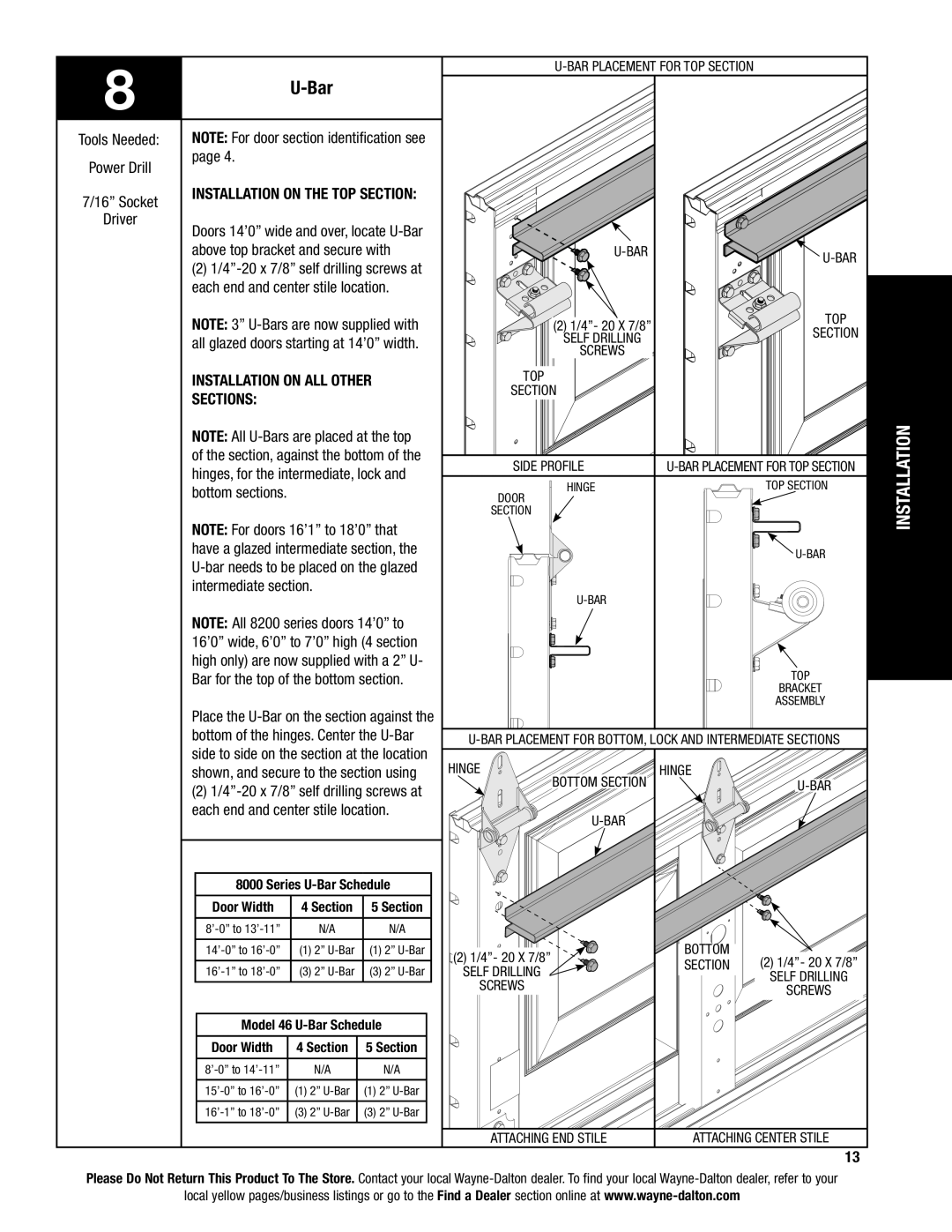
46 specifications
Wayne-Dalton 46 is a prominent garage door model known for its unique combination of durability, aesthetic appeal, and advanced technology. Designed specifically for residential properties, this door offers homeowners an array of features that enhance the overall functionality and style of their garages.One of the standout characteristics of the Wayne-Dalton 46 is its construction. Made with high-quality materials, these doors are crafted to withstand various weather conditions. They are built using a steel frame, which provides structural integrity and support, while the insulated core helps to maintain energy efficiency in the home. The insulation also minimizes noise from outside, creating a peaceful environment within the garage.
In terms of style, the Wayne-Dalton 46 offers multiple design options to suit different architectural preferences. Homeowners can choose from various panel styles and colors, allowing for customization that complements the exterior of their homes. The door can be finished with a smooth or textured surface, adding to its visual appeal. Additionally, the Wayne-Dalton 46 features decorative hardware options, providing a touch of elegance and sophistication.
Technological innovation is another key aspect of the Wayne-Dalton 46. Equipped with the latest in garage door technology, these doors come with advanced safety features, including pinch-resistant construction, which helps to prevent injuries during operation. The door’s reliable opening mechanism ensures smooth and quiet operation.
Wayne-Dalton also incorporates smart technology into the 46 model. Homeowners have the option to equip their garage doors with Wi-Fi connectivity, allowing them to control the door remotely via smartphone apps. This feature adds convenience and security, enabling users to monitor their garage door's status and receive alerts in real time.
Maintenance of the Wayne-Dalton 46 is straightforward, thanks to its durable finish, which resists rust and corrosion. Regular inspections and basic upkeep will ensure longevity, providing a reliable garage door solution for years to come.
Overall, the Wayne-Dalton 46 stands out in the market for its impressive blend of style, durability, advanced features, and safety technology, making it an excellent choice for homeowners looking to enhance the appeal and functionality of their garages.
