FULL SIZE GAS CONVECTION OVENS - REMOVAL AND REPLACEMENT OF PARTS
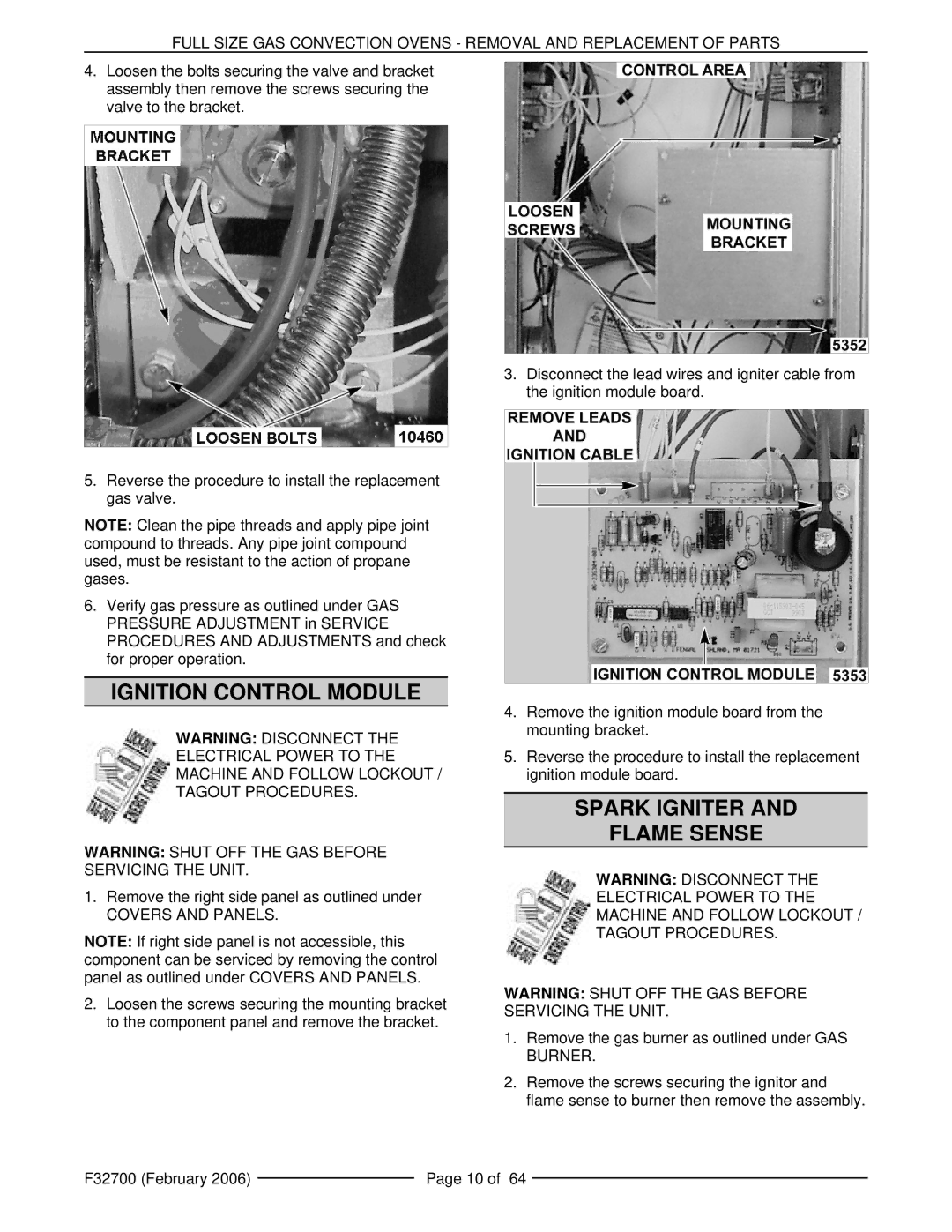
4.Loosen the bolts securing the valve and bracket assembly then remove the screws securing the valve to the bracket.
5.Reverse the procedure to install the replacement gas valve.
NOTE: Clean the pipe threads and apply pipe joint compound to threads. Any pipe joint compound used, must be resistant to the action of propane gases.
6.Verify gas pressure as outlined under GAS PRESSURE ADJUSTMENT in SERVICE PROCEDURES AND ADJUSTMENTS and check for proper operation.
IGNITION CONTROL MODULE
WARNING: DISCONNECT THE
ELECTRICAL POWER TO THE
MACHINE AND FOLLOW LOCKOUT /
TAGOUT PROCEDURES.
WARNING: SHUT OFF THE GAS BEFORE SERVICING THE UNIT.
1.Remove the right side panel as outlined under
COVERS AND PANELS.
NOTE: If right side panel is not accessible, this component can be serviced by removing the control panel as outlined under COVERS AND PANELS.
2.Loosen the screws securing the mounting bracket to the component panel and remove the bracket.
3.Disconnect the lead wires and igniter cable from the ignition module board.
4.Remove the ignition module board from the mounting bracket.
5.Reverse the procedure to install the replacement ignition module board.
SPARK IGNITER AND
FLAME SENSE
WARNING: DISCONNECT THE
ELECTRICAL POWER TO THE
MACHINE AND FOLLOW LOCKOUT /
TAGOUT PROCEDURES.
WARNING: SHUT OFF THE GAS BEFORE SERVICING THE UNIT.
1.Remove the gas burner as outlined under GAS BURNER.
2.Remove the screws securing the ignitor and flame sense to burner then remove the assembly.
F32700 (February 2006) |
| Page 10 of 64 |
|
