Introduction
Preparing for Installation
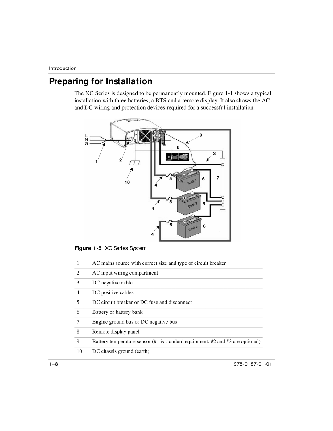
The XC Series is designed to be permanently mounted. Figure
| L |
|
|
|
| 9 |
|
|
| N |
|
|
|
|
|
|
|
| G |
|
|
| 8 |
|
|
|
|
|
|
|
|
|
|
| |
|
|
|
|
|
|
| 3 |
|
|
| 1 | 2 |
|
|
|
| |
|
|
|
|
|
|
| ||
|
|
|
| 10 | 5 | 6 | 7 |
|
|
|
|
| 4 |
|
|
| |
|
|
|
|
|
|
|
| |
|
|
|
|
| 5 | 6 |
|
|
|
|
|
|
| 4 |
|
| |
|
|
|
|
|
|
|
| |
|
|
|
|
| 5 | 6 |
|
|
|
|
|
|
| 4 |
|
|
|
| Figure |
|
|
|
| |||
1 |
| AC mains source with correct size and type of circuit breaker | ||||||
| ||||||||
|
|
|
|
|
|
| ||
2 |
| AC input wiring compartment |
|
|
| |||
|
|
|
|
|
|
|
| |
3 |
| DC negative cable |
|
|
|
| ||
|
|
|
|
|
|
|
| |
4 |
| DC positive cables |
|
|
|
| ||
|
|
|
|
|
|
| ||
5 |
| DC circuit breaker or DC fuse and disconnect |
|
|
| |||
|
|
|
|
|
|
|
| |
6 |
| Battery or battery bank |
|
|
|
| ||
|
|
|
|
|
|
| ||
7 |
| Engine ground bus or DC negative bus |
|
|
| |||
|
|
|
|
|
|
|
| |
8 |
| Remote display panel |
|
|
|
| ||
|
|
|
|
| ||||
9 |
| Battery temperature sensor (#1 is standard equipment. #2 and #3 are optional) | ||||||
|
|
|
|
|
|
|
| |
10 |
| DC chassis ground (earth) |
|
|
|
| ||
|
|
|
|
|
|
|
|
|
|
|
|
|
|
|
|
|
|
|
|
|
|
| ||||