English
Connecting external components to this unit
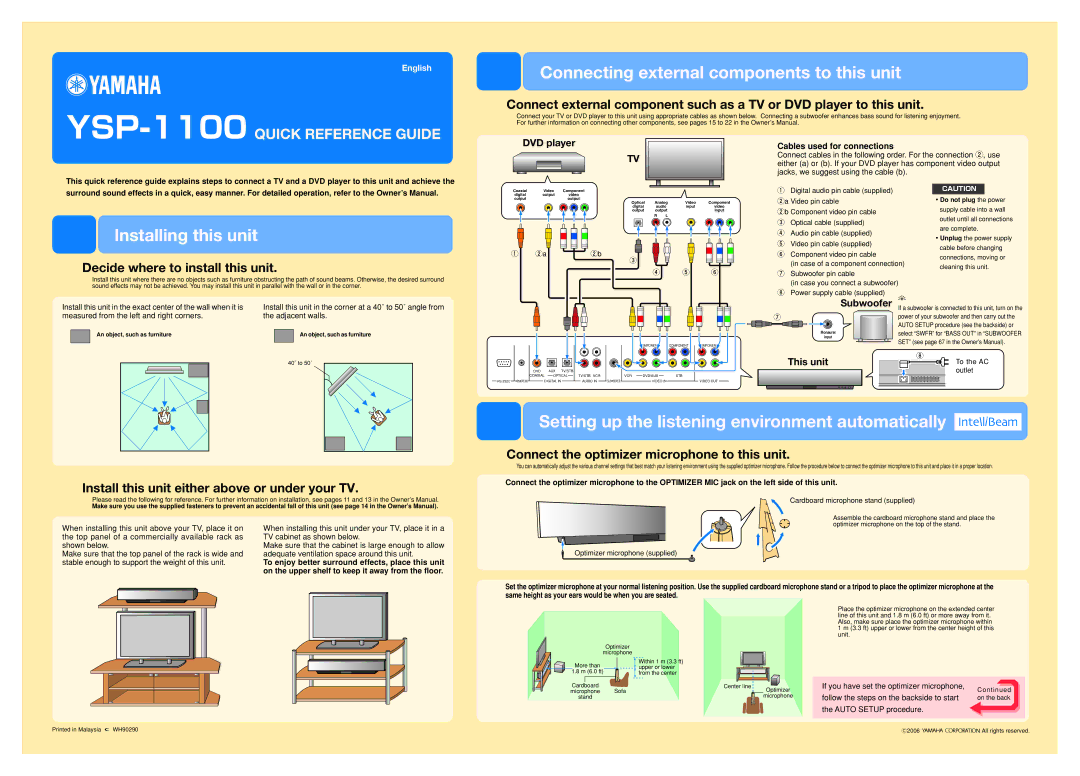
Connect external component such as a TV or DVD player to this unit.
Connect your TV or DVD player to this unit using appropriate cables as shown below. Connecting a subwoofer enhances bass sound for listening enjoyment. For further information on connecting other components, see pages 15 to 22 in the Owner’s Manual.
DVD player
TV
Cables used for connections
Connect cables in the following order. For the connection 2, use either (a) or (b). If your DVD player has component video output jacks, we suggest using the cable (b).
This quick reference guide explains steps to connect a TV and a DVD player to this unit and achieve the surround sound effects in a quick, easy manner. For detailed operation, refer to the Owner’s Manual.
Installing this unit
Decide where to install this unit.
Install this unit where there are no objects such as furniture obstructing the path of sound beams. Otherwise, the desired surround sound effects may not be achieved. You may install this unit in parallel with the wall or in the corner.
Coaxial | Video | Component |
digital | output | video |
output |
| output |
Optical | Analog | Video | Component | |||
digital | audio | input | video | |||
output | output |
| input | |||
|
|
| R | L |
|
|
|
|
|
|
|
|
|
|
|
|
|
|
|
|
1 2a | 2b |
3
4 5 6
1Digital audio pin cable (supplied)
2a Video pin cable
2b Component video pin cable
3Optical cable (supplied)
4Audio pin cable (supplied)
5Video pin cable (supplied)
6Component video pin cable
(in case of a component connection)
7Subwoofer pin cable
(in case you connect a subwoofer)
8Power supply cable (supplied)
CAUTION
・Do not plug the power supply cable into a wall outlet until all connections are complete.
・Unplug the power supply cable before changing connections, moving or cleaning this unit.
Install this unit in the exact center of the wall when it is | Install this unit in the corner at a 40˚ to 50˚ angle from | |||||||||||
measured from the left and right corners. | the adjacent walls. | |||||||||||
|
| An object, such as furniture |
|
| An object, such as furniture | |||||||
|
|
|
| |||||||||
|
|
|
|
|
|
|
|
|
|
|
|
|
|
|
|
|
|
|
|
|
| 40˚ to 50˚ |
|
| |
|
|
|
|
|
|
|
|
| ||||
|
|
|
|
|
|
|
|
|
|
|
|
|
|
|
|
|
|
|
|
|
|
|
|
|
|
|
|
|
|
|
|
|
|
|
|
|
|
|
|
|
|
|
|
|
| COMPONENT | COMPONENT | COMPONENT |
| DVD |
| AUX | TV/STB |
|
|
|
|
|
| COAXIAL | OPTICAL | TV/STB VCR | VCR | DVD/AUX | STB |
| ||
REMOTE IN | DIGITAL IN |
| AUDIO IN | SUBWOOFER | VIDEO IN |
| VIDEO OUT | ||
Subwoofer | y | |
| If a subwoofer is connected to this unit, turn on the | |
7 | power of your subwoofer and then carry out the | |
| AUTO SETUP procedure (see the backside) or | |
Monaural | select “SWFR” for “BASS OUT” in “SUBWOOFER | |
input | ||
SET” (see page 67 in the Owner’s Manual). | ||
| ||
This unit | 8 | |
To the AC | ||
| outlet |
Install this unit either above or under your TV.
Please read the following for reference. For further information on installation, see pages 11 and 13 in the Owner’s Manual.
Make sure you use the supplied fasteners to prevent an accidental fall of this unit (see page 14 in the Owner’s Manual).
When installing this unit above your TV, place it on | When installing this unit under your TV, place it in a | ||||
the top panel of a commercially available rack as | TV cabinet as shown below. | ||||
shown below. | Make sure that the cabinet is large enough to allow | ||||
Make sure that the top panel of the rack is wide and | adequate ventilation space around this unit. | ||||
stable enough to support the weight of this unit. | To enjoy better surround effects, place this unit | ||||
|
|
|
|
| on the upper shelf to keep it away from the floor. |
|
|
|
|
|
|
|
|
|
|
|
|
|
|
|
|
|
|
Setting up the listening environment automatically 
Connect the optimizer microphone to this unit.
You can automatically adjust the various channel settings that best match your listening environment using the supplied optimizer microphone. Follow the procedure below to connect the optimizer microphone to this unit and place it in a proper location.
Connect the optimizer microphone to the OPTIMIZER MIC jack on the left side of this unit.
Cardboard microphone stand (supplied)
Assemble the cardboard microphone stand and place the optimizer microphone on the top of the stand.
Optimizer microphone (supplied)
Set the optimizer microphone at your normal listening position. Use the supplied cardboard microphone stand or a tripod to place the optimizer microphone at the same height as your ears would be when you are seated.
Optimizer
microphone
More than | Within 1 m (3.3 ft) |
upper or lower | |
1.8 m (6.0 ft) | from the center |
Cardboard | Sofa | Center line | Optimizer |
microphone |
| ||
stand |
|
| microphone |
Place the optimizer microphone on the extended center line of this unit and 1.8 m (6.0 ft) or more away from it. Also, make sure place the optimizer microphone within 1 m (3.3 ft) upper or lower from the center height of this unit.
If you have set the optimizer microphone, | Continued | |
follow the steps on the backside to start | ||
on the back | ||
the AUTO SETUP procedure. |
| |
|
|
Printed in Malaysia  WH90290
C2006 


 All rights reserved.