FORM
Electrical Notes (Continued)
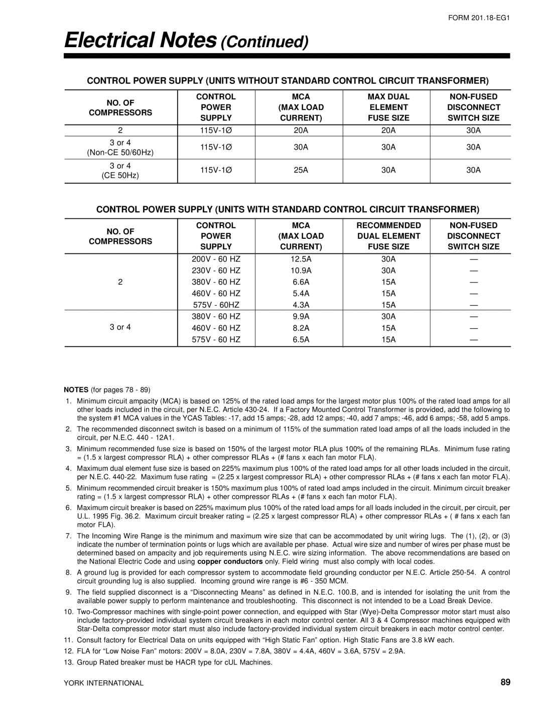
CONTROL POWER SUPPLY (UNITS WITHOUT STANDARD CONTROL CIRCUIT TRANSFORMER)
NO. OF | CONTROL | MCA | MAX DUAL | ||
POWER | (MAX LOAD | ELEMENT | DISCONNECT | ||
COMPRESSORS | |||||
SUPPLY | CURRENT) | FUSE SIZE | SWITCH SIZE | ||
| |||||
|
|
|
|
| |
2 | 20A | 20A | 30A | ||
|
|
|
|
| |
3 or 4 | 30A | 30A | 30A | ||
|
|
|
| ||
|
|
|
|
| |
3 or 4 | 25A | 30A | 30A | ||
(CE 50Hz) | |||||
|
|
|
| ||
|
|
|
|
|
CONTROL POWER SUPPLY (UNITS WITH STANDARD CONTROL CIRCUIT TRANSFORMER)
NO. OF | CONTROL | MCA | RECOMMENDED | ||
POWER | (MAX LOAD | DUAL ELEMENT | DISCONNECT | ||
COMPRESSORS | |||||
SUPPLY | CURRENT) | FUSE SIZE | SWITCH SIZE | ||
| |||||
|
|
|
|
| |
| 200V - 60 HZ | 12.5A | 30A | — | |
| 230V - 60 HZ | 10.9A | 30A | — | |
2 | 380V - 60 HZ | 6.6A | 15A | — | |
| 460V - 60 HZ | 5.4A | 15A | — | |
| 575V - 60HZ | 4.3A | 15A | — | |
| 380V - 60 HZ | 9.9A | 30A | — | |
3 or 4 | 460V - 60 HZ | 8.2A | 15A | — | |
| 575V - 60 HZ | 6.5A | 15A | — | |
|
|
|
|
|
NOTES (for pages 78 - 89)
1.Minimum circuit ampacity (MCA) is based on 125% of the rated load amps for the largest motor plus 100% of the rated load amps for all other loads included in the circuit, per N.E.C. Article
2.The recommended disconnect switch is based on a minimum of 115% of the summation rated load amps of all the loads included in the circuit, per N.E.C. 440 - 12A1.
3.Minimum recommended fuse size is based on 150% of the largest motor RLA plus 100% of the remaining RLAs. Minimum fuse rating = (1.5 x largest compressor RLA) + other compressor RLAs + (# fans x each fan motor FLA).
4.Maximum dual element fuse size is based on 225% maximum plus 100% of the rated load amps for all other loads included in the circuit, per N.E.C.
5.Minimum recommended circuit breaker is 150% maximum plus 100% of rated load amps included in the circuit. Minimum circuit breaker rating = (1.5 x largest compressor RLA) + other compressor RLAs + (# fans x each fan motor FLA).
6.Maximum circuit breaker is based on 225% maximum plus 100% of the rated load amps for all loads included in the circuit, per circuit, per U.L. 1995 Fig. 36.2. Maximum circuit breaker rating = (2.25 x largest compressor RLA) + other compressor RLAs + ( # fans x each fan motor FLA).
7.The Incoming Wire Range is the minimum and maximum wire size that can be accommodated by unit wiring lugs. The (1), (2), or (3) indicate the number of termination points or lugs which are available per phase. Actual wire size and number of wires per phase must be determined based on ampacity and job requirements using N.E.C. wire sizing information. The above recommendations are based on the National Electric Code and using copper conductors only. Field wiring must also comply with local codes.
8.A ground lug is provided for each compressor system to accommodate field grounding conductor per N.E.C. Article
9.The field supplied disconnect is a “Disconnecting Means” as defined in N.E.C. 100.B, and is intended for isolating the unit from the available power supply to perform maintenance and troubleshooting. This disconnect is not intended to be a Load Break Device.
10.
11.Consult factory for Electrical Data on units equipped with “High Static Fan” option. High Static Fans are 3.8 kW each.
12.FLA for “Low Noise Fan” motors: 200V = 8.0A, 230V = 7.8A, 380V = 4.4A, 460V = 3.6A, 575V = 2.9A.
13.Group Rated breaker must be HACR type for cUL Machines.
YORK INTERNATIONAL | 89 |