Basic Operation
Operating with Projector Control
Light Function |
| Side Control | ||||||||||||||
Light function is used | to turn on the lights on the side | |||||||||||||||
control and around terminals. To turn off the lights, press |
|
|
|
|
|
|
|
|
|
|
| SHUTTER button | ||||
|
|
|
|
|
|
|
|
|
|
| ||||||
the Light button again. |
|
|
|
|
|
|
|
|
|
|
|
|
|
| LIGHT button | |
|
|
|
|
|
|
|
|
|
|
|
|
|
| |||
|
|
|
|
|
|
|
|
|
|
|
|
|
| |||
✔Note: |
|
|
|
|
|
|
|
|
|
|
|
|
|
| ||
|
|
|
|
|
|
|
|
|
|
|
|
| ZOOM button | |||
• The buttons on the side control except for the LIGHT button |
|
|
|
|
|
|
|
|
|
|
|
| FOCUS button | |||
and |
|
|
|
|
|
|
|
|
|
| LENS SHIFT button | |||||
|
|
|
|
|
|
|
|
|
| |||||||
is in |
|
|
|
|
|
|
|
|
|
|
|
|
|
|
| |
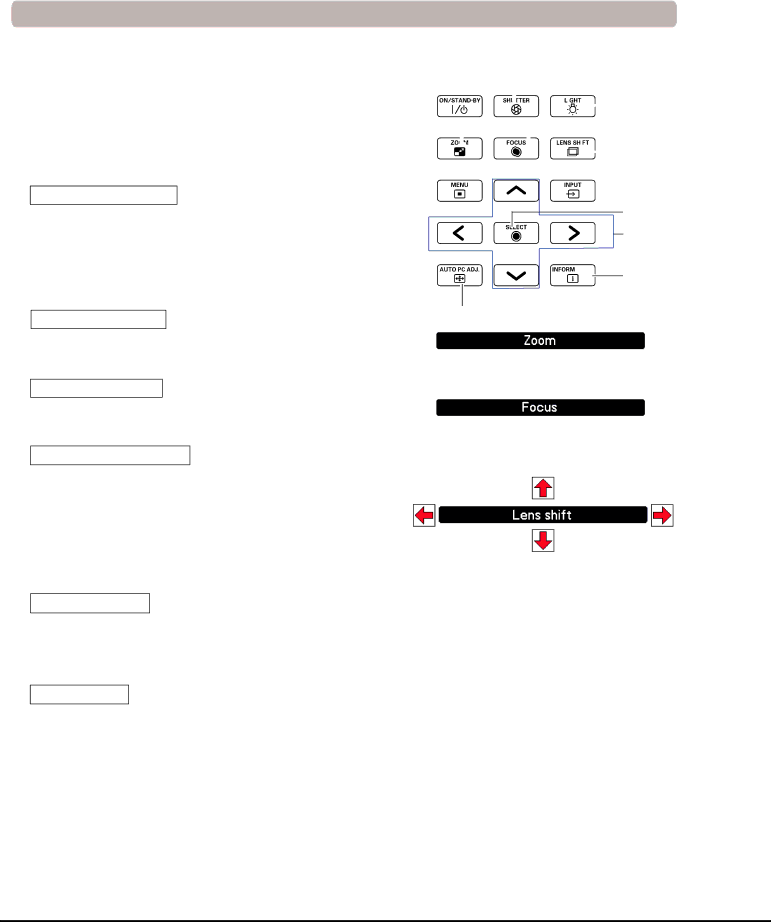
Auto PC Adjustment
Operates the Auto PC Adj. function. The computer screen adjustment can be done easily by pressing this button. See page 37 for details.
Zoom Adjustment
Press the ZOOM button and “Zoom” will be displayed on the screen. And then press the Point ed buttons to zoom in and out the image.
Focus Adjustment
Press the FOCUS button and “Focus” will be displayed on the screen. And then press the Point ed buttons to adjust the focus of the image.
Lens Shift Adjustment
Press the LENS SHIFT button and “Lens shift” will be displayed on the screen. Use the Pointed ed7 8 buttons to position the projection image to the desired point without having picture distortion.
Press and hold the LENS SHIFT button for more than 5 seconds to return the lens to the central position. See page 18 for details.
SELECT button
POINT buttons
![]()
![]()
![]() INFORMATION button
INFORMATION button
AUTO PC ADJ. buttons
Shutter Function
Shutter function allows you to completely block out light to the screen. Press the SHUTTER button to close the shutter inside the projector. To open up the shutter, press the SHUTTER button again. Refer to p.66 for detail of setting for the Shutter function.
✔Note:
•The arrow disappears at the maximum lens shift in each direction.
•The arrows turn red when the lens shift comes to the center position of the screen.
Information
Information display can be used to confirm the current operating condition of the projector and the signal being projected through the projector.
Press the INFORMATION button to toggle between the current and next Information menus and the cancellation of menu display.
The Information menu can also be selected from the menu.
✔Note:
•The SHUTTER button on the side control and the remote control cannot be effective when Shutter Protection is On in the Setting menu. (p.66)
•The SHUTTER indicator on the projector's top lights blue when the shutter is closed. (pp.13, 86)
•The projector will shut down automatically when the set time on shutter management has passed. (p.66)
•The Power management function does not work when the shutter is closed. (p.63)
28