Ingersoll-Rand 4575759 user manual Diagnostics and Troubleshooting, Introduction

Page 75

Sensor I® Expert User Manual

DIAGNOSTICS AND TROUBLESHOOTING

Introduction

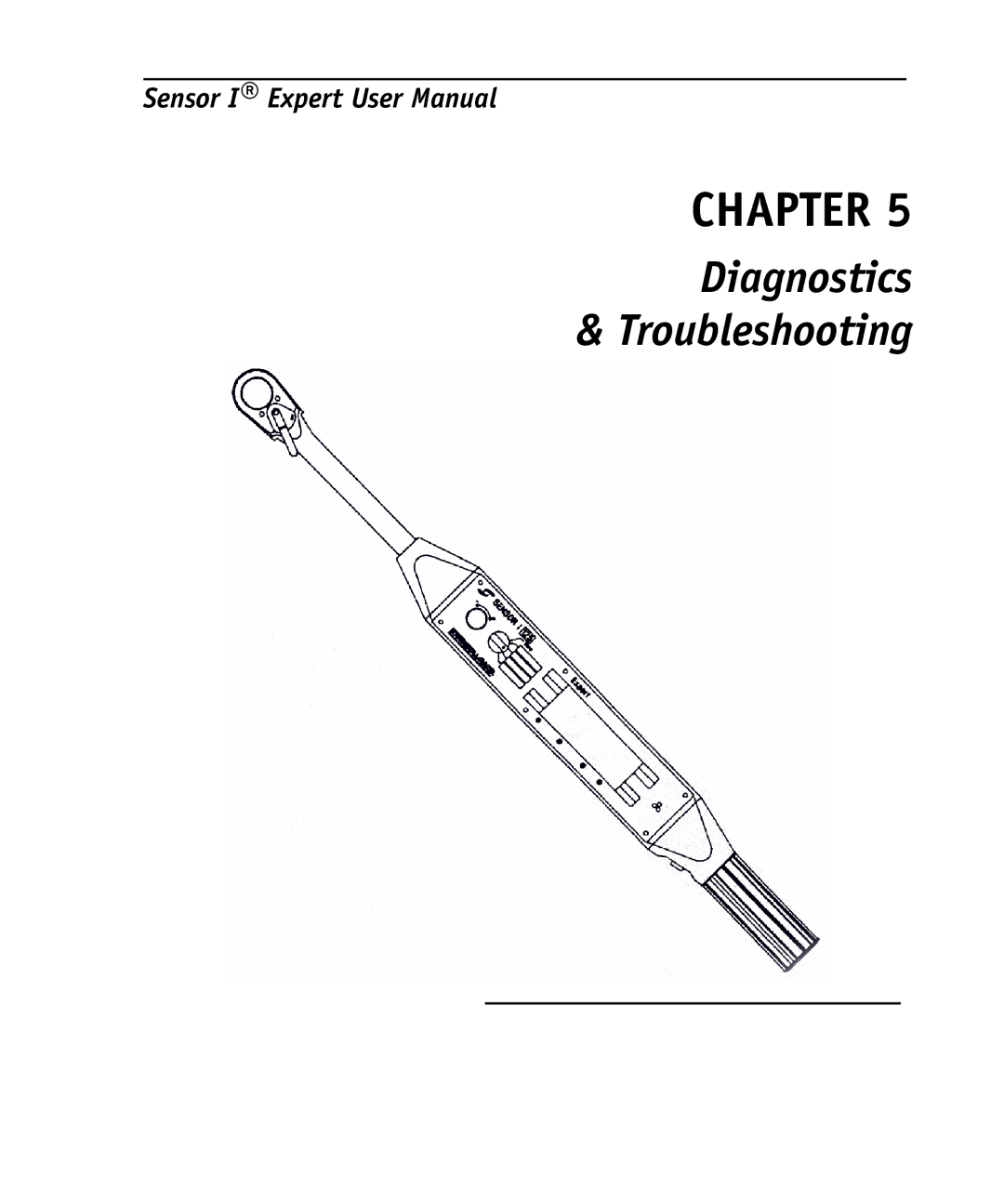
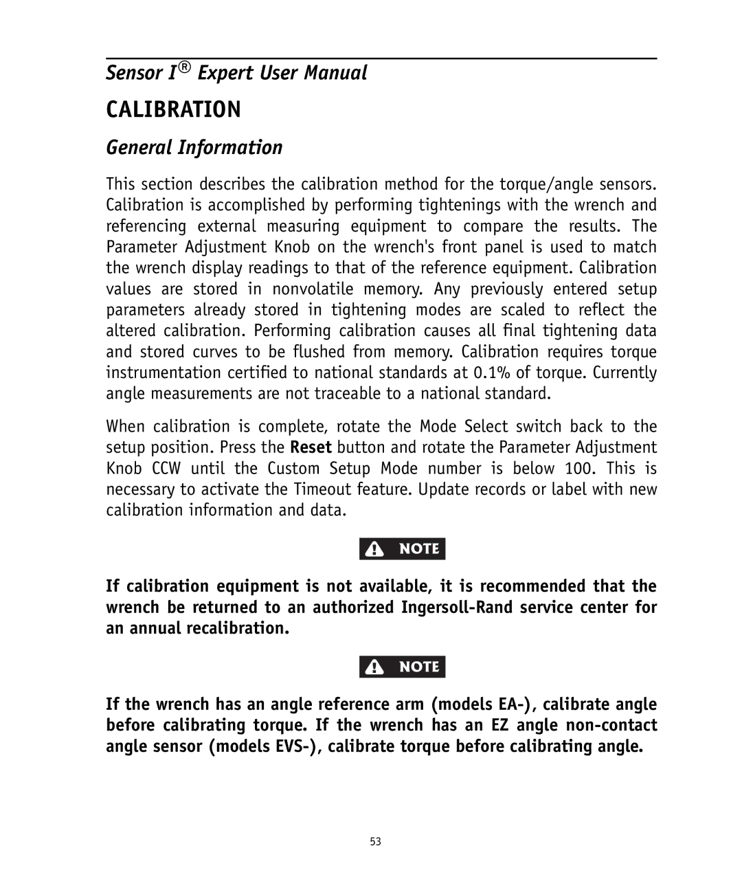
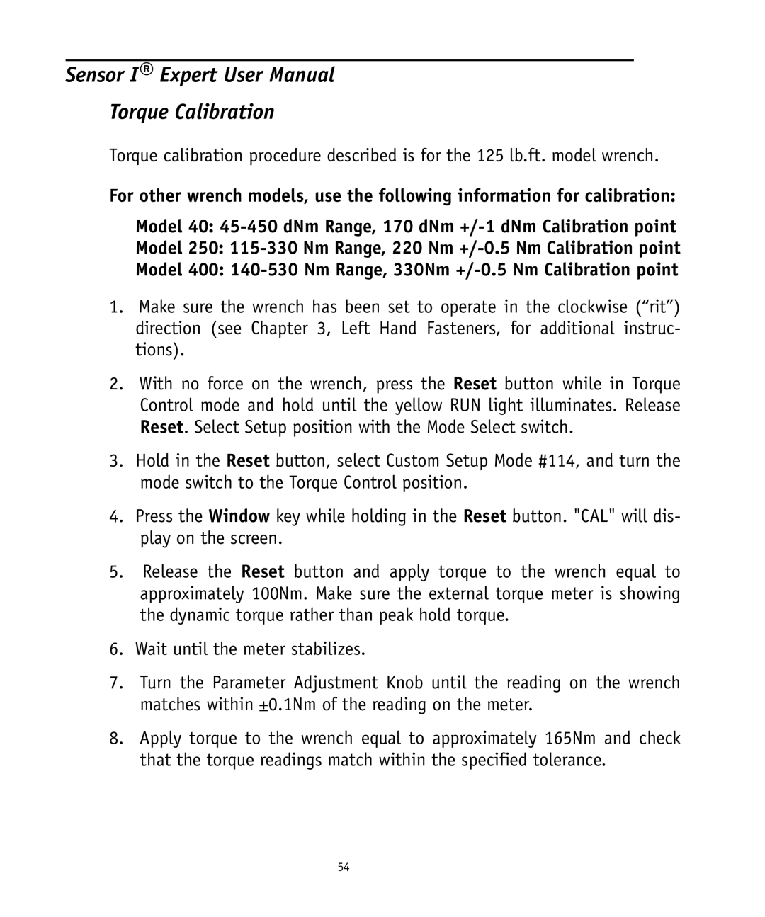
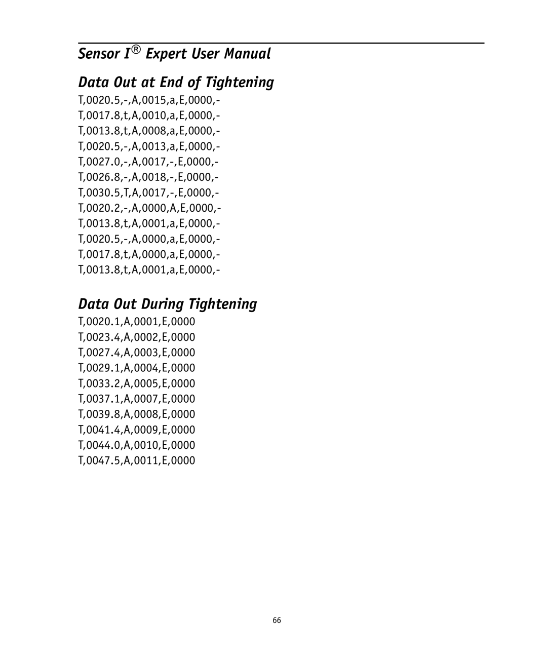
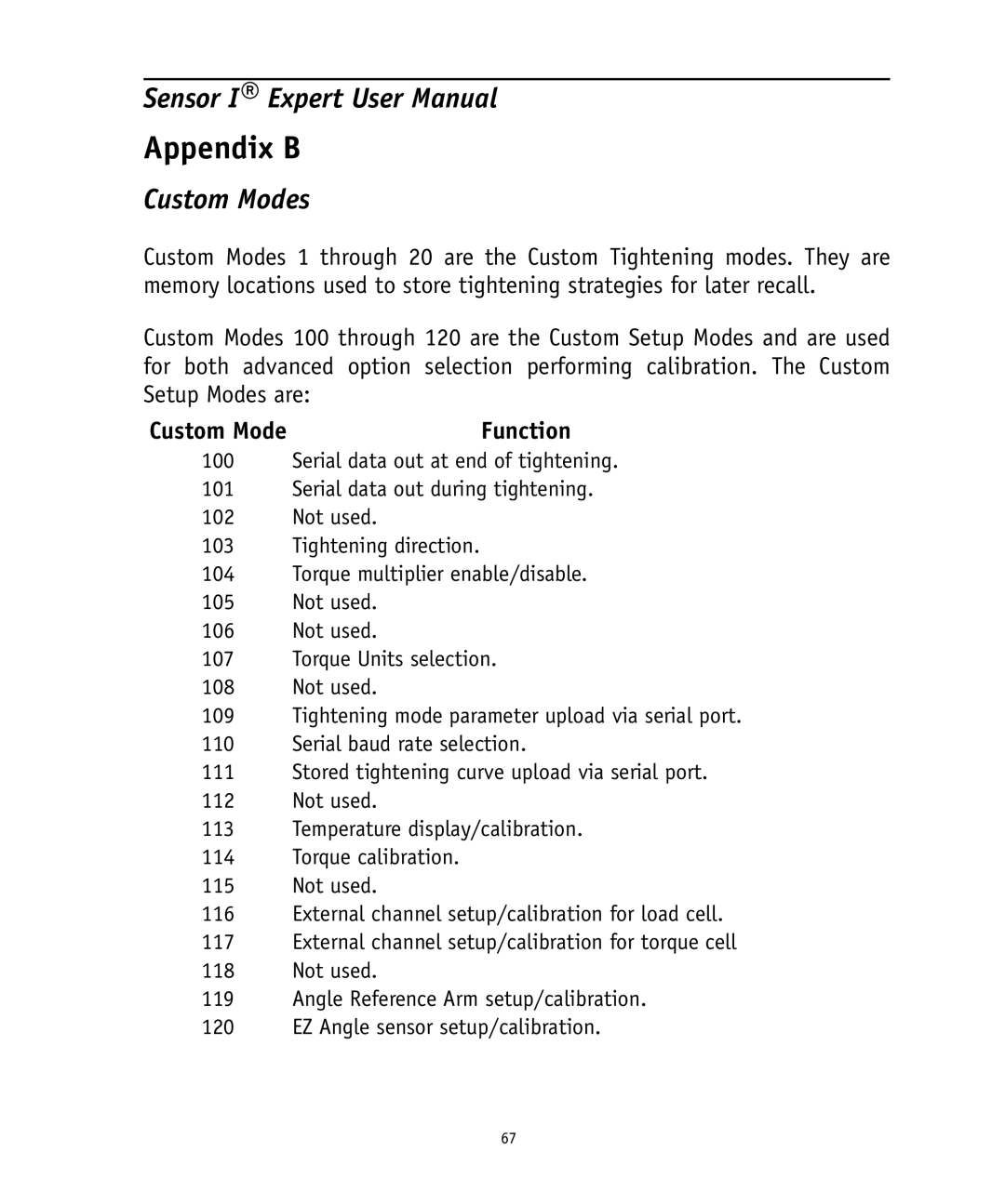
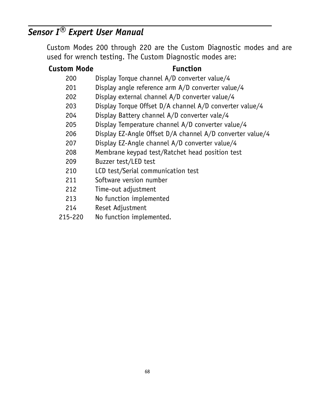
This chapter provides troubleshooting information using the built-in diagnostic test modes. Tests can be performed by selecting Custom Setup Mode numbers between 200 and 212. When diagnostics are complete, rotate the Mode Selection switch to Setup and turn the parameter adjustment knob to select a Custom Setup Mode number below 20. Then turn the Mode Selection switch to a Primary Mode to reactivate the wrench Timeout feature. If any of the following tests are beyond values listed, go back to the primary mode and reset the wrench. Also make sure the wrench has not had any torque applied. If tests continue to be out of value limits, please contact an authorized Ingersoll-Randservice center shown in Appendix D.

Torque Channel A/D Display (Custom Mode #200)

1.The value displayed should be in the range 25-29 when no torque is applied to the wrench. Applying torque in the clockwise (CW) direction will cause this value to increase. Applying torque in the opposite (CCW) direction will cause the displayed value to decrease.

2.If Custom Mode #103 has been set for CCW tightening ("-LEF"), the dis- play will indicate a value between 846 and 853. CW torque then decreases the number, and CCW increases it.

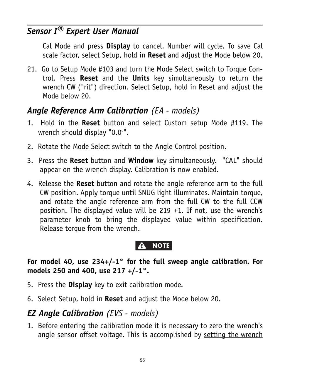
Angle Reference Arm Test Mode (EA - Models, Custom Mode

#201)

If the wrench has been calibrated, the display value will be 15 ±5 at the low end (CW). Rotate the angle reference arm between full CW and full CCW. The change in value as the arm is moved should have no discontinuities. At the high end (CCW), the value will be in the range of 560 ±5. For Models 125, 250 and 400, if the values are not correct, loosen the setscrew on the angle reference arm lever and rotate the lever relative to the shaft until the value
49

Image 75
Contents Sensor I Expert Electronic Wrenches Page Form 7266 Version 005, 08/04 Sensor I ExpertPage Page Page Wrench Reset To Dynamically Audit Residual Torque Dynamic Audit≤ 2d To Tighten to a Torque To Tighten to an AngleTo Tighten to Yield Page Page Table of Contents Page Table of Contents Battery Charging Introduction ChapterPage Introduction Page Tool Description Page Tool Description Technical Data 125 250 400Page Expert 125, 250 and 400 Models Functions of ComponentsExpert Control System Status Lights Mode Selector Switch Digital Display Page Membrane Keys Audible Alarm Item no Longer in USE Page Operation Instructions Page General Information Wrench Operation InstructionsSetting Torque Units Torque Control Tightening Procedure Page Dynamic Audit Page Yield Control Page Angle Control Page Cycle Counter Resetting the Cycle CounterQuality Control Limits and Statistics Setup and Viewing Quality Control LimitsDeleting Quality Control Limits Use of Quality Control Limits Mean Standard Deviation Process Capability Index StatisticsCustom Tightening Modes Setup and Storage of Custom Tightening ModesIdentifying Custom Tightening Modes Retrieving Custom Tightening ModesClearing Custom Tightening Modes Data Storage and Retrieval Setup of Wrench for Data UploadLast two numerals are not shown on the wrench display Data Out During TighteningData Out at End of Tightening Parameter Dump End of Tightening Data Dump Tightening Curve Storage Tightening Curve Data Dump Torque Multiplier Function Setup of a Torque MultiplierPage Use of a Torque Multiplier Left Hand FastenersReset Adjustment EVS-models only Page Reset Adjustment Value Models 125, 250 Page Battery Charging Page Battery Charging Page Diagnostics Troubleshooting Page Introduction Diagnostics and TroubleshootingTorque Channel A/D Display Custom Mode #200 Angle Reference Arm Test Mode EA Models, Custom ModeBuzzer and LED Test Mode Custom Mode #209 Battery Level Test Mode Custom Mode #204EZ Angle Test Mode Custom Mode #207 Membrane Keypad Test Mode Custom Mode #208Time-out Adjustment Custom Mode #212 Software Version Number Test Custom Mode #211Page Calibration Page General Information CalibrationTorque Calibration Page EZ Angle Calibration EVS models Angle Reference Arm Calibration EA modelsPage Page Sample Data Reports Appendix aPage Sample Reports Parameter Dump Appendix aEnd of Tightening Data Dump Torque Torque Units Nm Tightening Curve Data DumpData Out During Tightening Data Out at End of TighteningPage Appendix B List Setup ModesPage Custom Modes Appendix BCustom Mode Appendix C Spare Parts ListPage Appendix C Spare Parts Listing ModelE40-STRP Spare Parts Listing Model 40E40-PR-LABEL Spare Parts Listing Model Spare Parts Listing Model 125 Spare Parts Listing Model Spare Parts Listing Model 250 Spare Parts Listing Model Spare Parts Listing Model 400 Page Appendix D Service CentersPage Appendix D Service CentersSensor I Expert Electronic Wrenches Save These INSTRUCTIONS. do not Destory Ingersoll-Rand Company