Power Switch "ON," Rail Cooling Switch "NORMAL" or "LOW" Position
When in the "NORMAL" position, RailFM operates continuously.
When in the "LOW" position, RailFM operates continuously when rail is cooling down and intermittently (per F9 setting) when rail cool down is achieved. See "II.D.4.a) Switch Settings" and "II.D.5. Service Menu."
2. Cabinet and
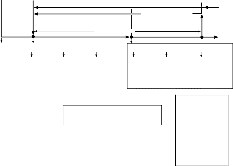
Cycle Steps ![]() 1. Start
1. Start
•
•
Initial startup begins here ![]()
![]()
2. Cool Down |
| 3. Cool Down Achieved |
| ||
|
|
|
Minimum 2 minute Comp delay if C and R were off
CTh and/or RTh reaches 3.6°F
(2°C) or more below setpoint
CTh and RTh in control
4.Cabinet Defrost
From 6 next page
RThor towarmssetpoint
CTh
To 4
next page
Rail Cooling
13
CabFM energized CLLV energized PH energized RailFM energized RLLV energized
C on | C off | C on |
R on | R on | R off |
CabFM energized | CabFM energized | CabFM energized |
CLLV energized | Comp energized | CLLV energized |
Comp energized | ConFM energized | Comp energized |
ConFM energized | PH energized | ConFM energized |
PH energized | RailFM energized | PH energized |
RailFM energized | RLLV energized | RailFM energized |
RLLV energized | CLLV | |
|
|
|
C off | C on |
R on | R off |
CabFM energized | CabFM energized |
Comp energized | CLLV energized |
ConFM energized | Comp energized |
PH energized | ConFM energized |
RailFM energized | PH energized |
RLLV energized | RailFM energized |
CLLV | RLLV |
C and R off
CabFM energized PH energized RailFM energized RLLV energized CLLV
•C
•C
•R
•R
Legend: