Hoshizaki
73168
service manual
Wiring Diagrams, HPR46A-D
Service Menu Chart
Alarm Signal
Dimension
Maintenance
Reset Options
Control Board Check Procedure
Controls and Adjustments
Refrigerant Recovery
Temperature Setpoint
Safety
Page 63
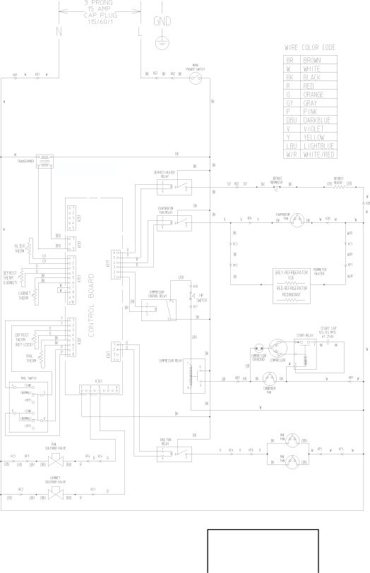
B. Wiring Diagrams
1.
HPR46A(-D)
Transformer Output
10V at 115V
*
*High Pressure Switch
Cut-out
490±10 PSIG
Cut-in
370±20 PSIG
63
Page 62
Page 64
Image 63
Page 62
Page 64
Contents
Superior Degree Reliability Number Issued Revised
Hoshizaki AMERICA, INC
Contents
Page
Page
Unit
Important Safety Information
Serious injury
Indicates important information about the use and care
Dimensions
Specifications Nameplate Ratings
II. General Information Construction
Power Switch ON, Rail Cooling Switch OFF
Power Switch ON, Rail Cooling Switch Normal or LOW
Sequence of Operation
Cabinet Defrost
Cool Down Restart
Rail Defrost
Cabinet Defrost Power Switch ON, Rail Cooling Switch OFF
Operation
Power Switch ON, Rail Cooling Switch OFF Cabinet
Rail Cooling
Power Switch ON, Rail Cooling Switch Normal or LOW Position
Cabinet and Rail Cooling
Control Board Location
Control Board
Control Board Layout
Front Rear
Compressor Short Cycle Protection
LED Display and Service Lock-Out
Alarm Signal
Service Menu
Controls and Adjustments
Switch Settings
Temperature Display
Temperature Setpoint
Energy Saving Mode
Cabinet Defrost
Temperature Correction Factor
Service Menu Access
Service Menu
Service Menu Chart
Alarm Signals
Control Board Check Procedure
Control Board Replacement
Thermistor Check
Perimeter Heater
Compressor Protector
Alarm Signals
III. Service Diagnosis
Alarm Priority Problem Reset, Corrections, and Adjustments
Reset Options
High Temperature Alarm E1
Low Temperature Alarm E2
Cabinet Defrost Alarm E3
High Condenser Temperature Alarm clogged filter E7
Defrost Thermistor cabinet Malfunction Alarm E8
Possible Causes
5a. Secondary Defrost Thermistor Rail, not used
Condenser Thermistor Malfunction Alarm E9
Service Chart
Control Board Alarms EA and ED
No Operation
Cabinet Cooling
Problem Possible Cause Remedy
Rail Cooling
Cabinet Defrost
Other
IV. Removal and Replacement of Components
Service for Refrigerant Lines
Refrigerant Recovery
Evacuation and Recharge R-404A
Brazing
Page
Refrigerant Recovery Procedure
Removal and Replacement of Refrigeration System Cartridge
Page
Refrigeration System Pump‑Down Procedure
Page
Defrost Thermistor Rail Thermistor
Removal and Replacement of Compressor
Removal and Replacement of Cabinet Evaporator
Removal and Replacement of Expansion Valve
Removal and Replacement of Liquid Line Valve
Removal and Replacement of Condenser
Removal and Replacement of Thermistors and Thermostat
Cabinet Thermistor
Defrost Thermistor
Rail Thermistor
Defrost Thermostat
Condenser Thermistor clogged filter
Removal and Replacement of Defrost Heater
Cabinet Fan Motor
Removal and Replacement of Fan Motors
Rail Fan Motor
Condenser Fan Motor
Door Re-Hinging and Drawer Conversion
Removal and Replacement of Door Gasket
Work Surface
Cleaning and Maintenance Instructions
Door/Drawer Gaskets
Rail and Rail Cover
Exterior
Cabinet Interior
Air Filter
Maintenance
Power Supply Connection
Rail Condensate Pan
Shutdown and Long Storage
HPR100A-D
Refrigeration Circuit VI. Technical Information
HPR46A-D
Wiring Diagrams
2a. HPR72A-D Auxiliary Code U-5 and Earlier
2b. HPR72A-D Auxiliary Code U-6 and Later
Awaiting Data
Related pages
All Diagram page
See chart on for New Balance 1200, 1400, 1500
Radar overlay doesnt appear on the chart screen for NorthStar Navigation 8000I
Diagrams for HP Enterprise 500
16. Circuit Diagram For Customer Interface Board PC14 Part 2 for Miller Electric Welder
Baking Chart for Jenn-Air FCG20500
Bar Chart for Marathon MAGNUM ROUTER
Wiring Diagrams for Bryant T2-PAC
Coolant System & Gear Box Selectors Diagram for King Canada KC-1440ML-6
Block Diagram for Intel 2804040
Hardware Overview System Block Diagram for Toshiba QOSMIO G20
How do I properly set the wash cycle on my
Indesit DIF 16
?
Top
Page
Image
Contents