Lanplex 2500 Extended Switching User Guide
3Com Corporation 5400 Bayfront Plaza Santa Clara, California
Contents
Default Route Address Resolution Protocol ARP
What Is Routing?
Overlapped IP VLANs
Example
Pruning
Mbone Multicast Routing Algorithms Flooding
Dvmrp Metric Value
Elements IPX Routing
Administering Routes
Administering interfaces LIS Interfaces
About Aarp
Displaying Interfaces
Displaying the ATM ARP Cache
Defining a Static Route
10-2
10-3
11-2
Displaying Routes Displaying the Multicast Cache
11-3
11-3 Modifying an Interface
MIB Objects 13-4 Alarms
What Is RMON?
12-11
12-12
Support from 3Com A-4 Returning Products for Repair A-4
About this Guide
When you configure your LANplex 2500 system
Introduction
Monitoring Rmon
List conventions that are used throughout this guide
Conventions
Icon Type Description Information Note
Instructions
LANplex 2500 Documentation
801-00322-000
LANplex 2500 Software Release Notes
2-5 ,
Module Installation Guides
About this Guide
Switching
Features
About LANplex
Extended
Switching software
Using Menus
Bridge Menu Hierarchy
IP Menu Hierarchy
IPX Menu Hierarchy
Appletalk Menu Hierarchy
Vlans on
For the network administrator
About VLANs
Vlan concept in LAN technology helps minimize broadcast
Vlans on the Lanplex System
Vlan Configuration Protocol Suite
SNA Services over Ethernet Ethertype
Ethertype, Snap PID
DECnet
Layer 3 Addressing Information
Switch Ports
About VLANs
Index 1 2 Data received on
VLAN, so the Default Vlan is used
IP port
Source port
Default None
So the Default Vlan is used
Data received on Is flooded on Because XNS port
System
158.103.122.2
Data received on Is flooded on Because IP subnet
On port IP subnet
158.103.123.2
About VLANs
Example of a Protocol-Sensitive Vlan Configuration
Vlan Examples Example
A Vlan Configuration with Servers on Separate 100BASE-T ports
Example
Vlans on the Lanplex System
Lanplex System
Bridging and Routing
Subnetted Architecture with LANplex Switching Hubs
Multiple Ports per Subnets with the LANplex 2500 System
Routing Models
Bridging
Bridging in the Traditional Bridging and Routing Model
Bridging in the LANplex Bridging and Routing Model
Routing in the LANplex Bridging and Routing Model
Bridging and Routing in the Lanplex System
Routing with IP Technology
IP Routing
OSI Model
Routing
Elements of IP
Section
Hardware-configured 48-bit addresses
Address Classes
How a Subnet Mask Is Applied to the IP Address
Shows the routing table of the router in Figure
Static Routes
Dynamic Routes Using RIP
Example of an ARP Cache
Example of ARP Cache Updated with ARP Reply
Transmission
Errors
Classical IP over
Routing with
Forwarding to Nodes within an LIS
References
Routing with IP Technology
Routing with IP Multicast
About IP
Multicast Routing
Provider
To a multicast router
Tunnels on page 6 for more information about tunnels
Multicast tunnel only if the Time-To-Live TTL value present
Flooding Spanning Trees Reverse Path Forwarding
Algorithms routing
Shows a simple network with five links
Simple Network Implemented Without Using Spanning Tree
Multicast
Interfaces
Which are described in this section
Routing with IP Multicast
IPX Routing
NetWare
Environment
NetWare Protocols and the OSI Reference Model
Be provided by protocols above IPX
Protocol RIP
Shows the IPX packet format
How IPX Routing Works
IPX Packet Routing
How IPX Routing Works
Service Advertising Protocol SAP
Elements
Intranetwork
Shows an example of a typical routing information table
Aging Timer The time since the network’s last update
Internetwork Service Information
IPX Packet Format
Routing with IPX
Server Information Table
Server Information Maintenance
Elements of IPX Routing
Routing with IPX
About AppleTalk
Routing in AN Appletalk Environment
AppleTalk
Network
Named Entities
AppleTalk Networks and AppleTalk Zones
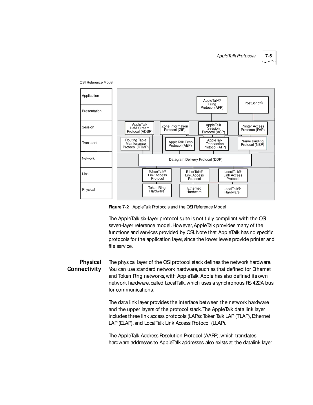
Protocols
AppleTalk Protocols and the OSI Reference Model
Routing in AN Appletalk Environment
AppleTalk Protocols
Network Router Interface
AppleTalk Protocols
Description language used by many printers
About Aarp
Mapping for both extended and nonextended networks
Another probe packet
About Aarp
Routing in AN Appletalk Environment
Administering Vlans
From the top level of the Administration Console, enter
Displaying Vlan Information
Describes these statistics
Example of a detailed display for the VLANs
Fields for Vlan Information Description Index
Layer
Defining Vlan Information
Vlan
Modifying Vlan Information
Information
Removing Vlan Follow these steps to remove a Vlan definition
Enter the indexes for the VLANs you want to remove Example
Administering Vlans
Administering
Administering IP Routing
Administering IP Routing
Ip interface summary Ip interface detail
Example summary display
Example detail display
Defining an IP LIS Interface
LIS interface example with both PVCs and SVCs
Atm Route Arp Detail
Accept the default yes if you want to delete the interface
Modifying an Interface
Removing an
Removing an Advertisement Address
Adding a Permanent Virtual Circuit PVC
Routes
Removing a Permanent Virtual Circuit PVC
Automatically
Interface Status Information Description Direct
Static Route was statically configured Learned
Timing out
Timed out
Displaying Routing Table
Flushing a Route
Removing a Route
Default route is immediately removed from the routing table
ARP Cache
Corresponding MAC addresses
Example display of the contents of the ARP cache
String from the top level of the Administration Console
Displaying the ARP
Cache
ATM ARP Servers
Administer the ATM ARP cache
Flushing the ARP Cache
ARP cache entries are immediately removed from the table
Removing an ATM ARP Server
ATM switch, such as 3Com’s CELLplex 7000 system
Ip atmArpServer arp Display
Removing an ATM ARP Cache Entry
UDP Helper
Bootp including Dhcp = Time = DNS =
Flushing the ATM
Are modified and then forwarded through the router
Displaying UDP Helper Information
Enabling Disabling IP Routing
Enabling Disabling Icmp Router Discovery
Setting the RIP
Mode
Operate in any of three modes
Pinging an IP Station
Enter the IP address of the station you want to ping
You may receive one of the following responses
Describes the IP statistics
Displaying IP Statistics
Administering IP Routing
IP Multicast Routing
Administering
Enabling
Enabling and Disabling Dvmrp
Disabling Igmp
Methods to make this determination
Administering IP
From the top level of the Administration Console, enter
Rate Limit
Example multicast interface configuration
Enabling Multicast Interfaces
Disabling Multicast Interfaces
Multicast Tunnels
Multicast Tunnels Administration Console, enter
IP address of the remote multicast router
Displaying
Defining a To define an IP multicast tunnel Multicast Tunnel
Removing a Multicast Tunnel
Tunnel is removed
Describes the fields in the route display
Displaying Routes
You are prompted for the multicast source address
Displaying the Multicast Cache
Following display shows the multicast cache configuration
Describes the fields in the cache display
Administering IP Multicast Routing
Administering IPX Routing
Address. Each address within the network should be unique
Define an associated interface
Formats and two Fddi encapsulation formats. The Ethernet
Is available for communications Up or unavailable Down
Defining an IPX
From the Administration Console top-level menu, enter
Ipx interface modify
Known to the router
Administration Console
Routers
Segment. a tic is approximately 55 milliseconds
As well as the routing table
Defining a Static Route
Console top-level menu, enter
Ipx route remove
Servers
Server table using the Administration Console
Defining a Static Server
Console top-level menu, enter
Enter the number of hops to the server. Example
From the Administration Console top-level menu, enter
Removing a Server To remove a server
Flushing Servers
Forwarding
Setting IPX
Enhanced RIP
Setting
Follow the IPX router implementation guidelines
Brackets, press Return at the prompt
Enter the SAP mode off, passive, or active. To use the value
Setting the SAP
Statistics
Displaying
Describers the IPX RIP statistics
Example below
SAP Requests
Describes the IPX SAP statistics
SAP Entries Number of servers in the server table
Been received
Ipx statistics forwarding
Describes the IPX forwarding statistics
Layer header errors
Hdr Errors
Errors in network layer header
No Routes
Administering Appletalk Routing
Associated AppleTalk interface
Defining an Interface
Displaying AppleTalk Interfaces
Removing an Interface
Enter the zone name
Appletalk route display
Following example shows a routing table display
12-7
Following example shows an Aarp cache display
Removing an Entry To remove an Aarp cache entry Cache
Displaying the Zone Table
Enter enable or disable at the prompt
Configuring Forwarding
Zone Table by Zones
Enter enable or disable at the checksum verification prompt
Enter enable or disable at the checksum generation prompt
Configuring Checksum
Pinging an AppleTalk Node
Describes the AppleTalk DDP statistics you can view
Following is an example of DDP summary statistics
Displaying Rtmp Information
An example of summary statistics is shown below
Describes the Rtmp statistics you can view
Displaying ZIP Information
Describes the ZIP statistics you can view
Displaying NBP Information
Describes the NBP statistics you can view
Remote Monitoring Rmon Technology
Remote Monitoring Rmon and the Lanplex System
Remote Monitoring Rmon Technology
Remote Monitoring Rmon Technology
Variable and trigger an alarm
Alarm
Segment being monitored
History
Information Base
Management
Example of an Rmon MIB Counter Object
Instances of when counters exceed their set threshold
Alarms
Application for details on setting up alarms
You misleading results
Manually Set Thresholds
Generates an alarm only under the following conditions
Appendix a Technical Support
Appendix
Variety of services. This appendix describes these services
Services
Technical Support
On-line Technical
Press Return to see the 3ComForum Main menu
Access by Digital Modem
Support from
Maintenance, application training, and support services
Your Network
Supplier
U.S. and Canada, call 800 876-3266 for customer service
3Com
Support contracts are available from 3Com
Numerics
Index
See also RIP See also SAP
Mbone
MIB
See also Fddi station statistics
Tunnels IP multicast 5-6