212 B
1WMPD4001448C
Page
Contents
ID Number and GLP Report
TERMS/INDEX
Features
Introduction
Compliance with EMC Directives
Compliance
Compliance with FCC Rules
Windows is a registered trademark of Microsoft Corporation
Rear of the display unit
Unpacking the Balance
Unpacking
Accessories
AC adapter ID label
Place the breeze break on the weighing pan so
Installing the Balance
How to install the breeze break
That it fits over the dust guard
How to disconnect the cable from the weighing unit
Rear of the weighing unit
Precautions
Before Use
When Building into a System
Lighter heavier than the true weight. This
After Use
Power Supply
During Use
Processing indicator
Display Symbols and KEY Operation
Display symbols
Stabilization indicator
Programmable-unit
Weighing Units
Units
Minimum Capacity
Capacity Minimum Display
Changing the Unit
Basic Operation Gram Mode
Weighing
01 mg 0.1 mg Standard range
Smart Range Function
Precision range/standard range value
Cond
Changing the Weighing Speed
Operation
Sensitive value
Calibration test
Calibration
Calibration
Display
Calibration
From previous
Key until CCout
Usable weights is shown on page 21, press
Calibration Test
Return to CC
From previous
Permit or Inhibit
Function Switch and Initialization
Switches
For details, refer to 20. Extended Functions
Initializing the Balance
Be sure to calibrate the balance after initialization
Display and Keys
Function Table
Structure and Sequence of the Function Table
Example
Details of the Function Table
Cpout Cp-t
Output Setting
Data output mode
Only the AD-4212B series
Interval time
Auto print polarity
Data memory
Time/Date output
ID number setting
Timeout
AK, Error code
Baud rate
Stability band width 5t-b
Description of the Class Environment, Display
Condition Cond
Hold function Hold Animal weighing mode, AD-4212A only
Display refresh rate 5pd
Capacity indicator g5i
Zero tracking trc
Decimal point pnt
Stream mode
Description of the Item Data output mode
Key mode
Tare at start p-tr
Interval memory mode
Key mode B
Key mode C
Description of the Item Data format
MT format 5if type
DP Dump print format 5if type
KF format 5if type
NU numerical format 5if type
Data number dout d-no
Description of the Data Format Added to the Weighing Data
ID number Dout 5-id
Date dout 5-td 2 or
Data Format Examples
Positive error
Negative error Space
20h
Confirming the time
Setting the time with part of the digits blinking
Clock and Calendar Function
Quitting the operation
Set the date using the following keys
Confirming the date
Five-level comparison results
Comparator Function
Three-level comparison results
Setting the upper/lower limit values
Indicates a space 20h
Confirming the upper/lower limit values
When three-level comparison is selected
When five-level comparison is selected
Adding the comparison results AD-4212A only
Display character set
Setting the ID Number
ID Number and GLP Report
Calibration report
When the setting is info
GLP Report
Set the following parameters to output the report
Calibration test report using an external weight
End block
Title block and end block
Weighing data
Storing a sample unit mass
Counting Mode PC
Selecting the counting mode
Counting mode using the Acai function
Counting operation
Reading the percentage
Selecting the percent mode
Storing the 100% reference mass
Releasing Clr
Balance displays End Returns to the weighing mode
Data Memory
Key until SClr no
Key is pressed while the displayed value is
Memory for Weighing Data
Storing the weighing data
Stable, the balance stores the weighing data
Recalling the memory data
Setting the function table
Press the CAL key to return to the weighing mode
Transmitting all memory data at one time
Deleting all memory data at one time
Transmitting the memory data
Memory for Calibration and Calibration Test Data
Storing the calibration and calibration test data
Deleting the memory data
Recalling the unit mass
Memory for Unit Mass in the Counting Mode
Key To cancel the operation and go to step
Key To increase the unit mass number by one
Memory for Upper/lower limit values
Inputting the upper/lower limit values 3-level comparison
Switching the upper/lower limit values 3-level comparison
Confirming the coefficient
Setting the coefficient
Using the function
Selecting the programmable-unit
Sub 25 pin numbers Sub 25 pin assignments
RS-232C
External contact input
Use a shielded
Cable
Use a shielded cable
AD-8121B settings
Mode Prt
When multiple lines are to be printed, set the parameter to
Connection to Peripheral Equipment
RsCom
Using Windows Communication Tools WinCT
Connection to a Computer
RsKey
Using the WinCT software, the balance can do the following
Commands to query weighing data
Commands
Command List
Commands to control the balance
Acknowledge Code and Error Codes
Control Using CTS and RTS
Settings Related to RS-232C
Connector Pin Nos. and Specifications
Cable
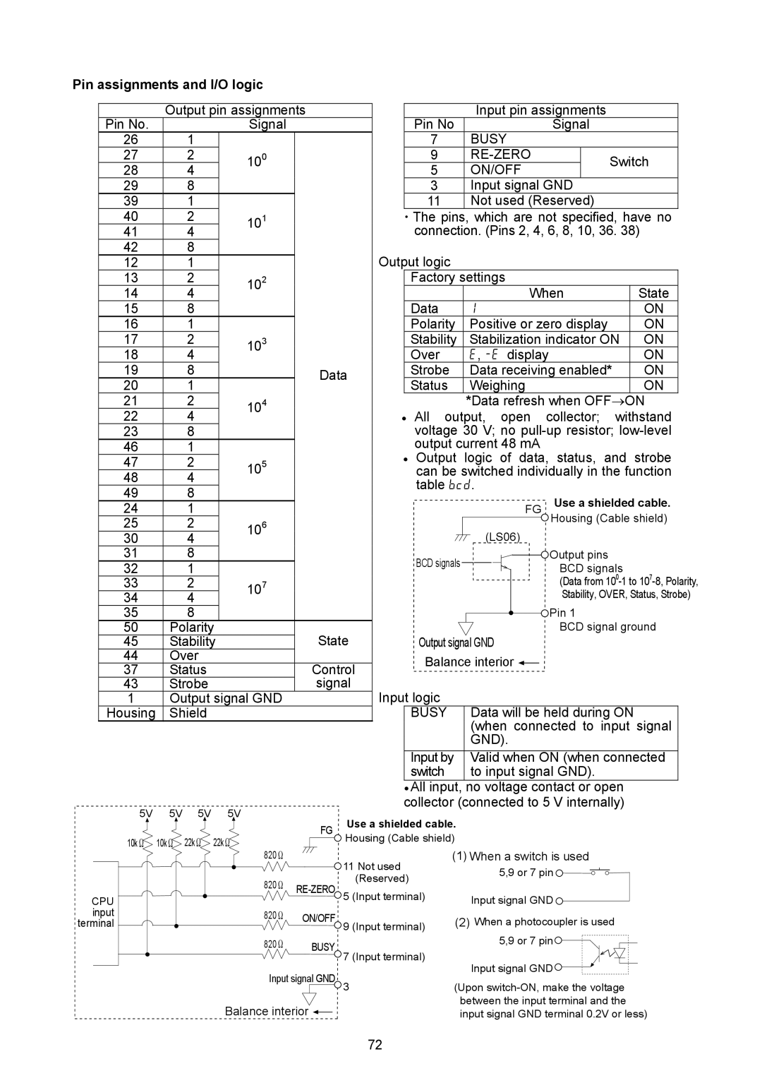
Pin assignments and I/O logic
On, T off 100 m sec or longer
OP-01 installation procedure
Timing chart
Extended Functions AD-4212A only
Page
Description of Averaging range and Averaging time
Averaging range f1-b and averaging time f1-t
Check the balance performance using the self-check function
Maintenance
Troubleshooting
Checking the Balance Performance and Environment
Sample and container
Operating environment
Weighing method
Error Codes
Memory type error
Unit mass error
Clock battery error
EC, E00 Communications error
Asking For Repair
Specifications
Power receptacle type Power consumption
Calibration weight provided
Display Dimensions 237 W × 150 D × 155 H mm Mass
Counting Minimum unit mass Mode
Pan support can be removed
Using the pan support
Designing a Special Weighing PAN
Pan boss can not be removed
Using the pan boss
Shock absorber specifications
AD-4212A-200
Mass of the special weighing pan AD-4212A series balance
AD-4212A-100
AD-4212A-600
AD-4212A-1000
Mass of the special weighing pan AD-4212B series balance
AD-4212B-101/102
AD-4212B-201
AD-4212B-301
Installing the Display Unit
Installing in a panel
Secure the weighing unit from above
Attachment Procedure
Attaching the Mounting Fixtures
Same for all the models
External Dimensions
Display unit
Weighing unit
Weighing unit with the mounting fixtures attached
AD-1683 DC static eliminator
Options
AD-8121B Printer
AD-1684 Electrostatic field meter
OP-08 Ethernet interface
OP-20 Metal leveling foot
Index
TERMS/INDEX
Terms
Cp fnc
Bep
Cl adj
Cp HH
Off
G5i
Pnt
Rng
Trc
5pd
5t-b
Memo