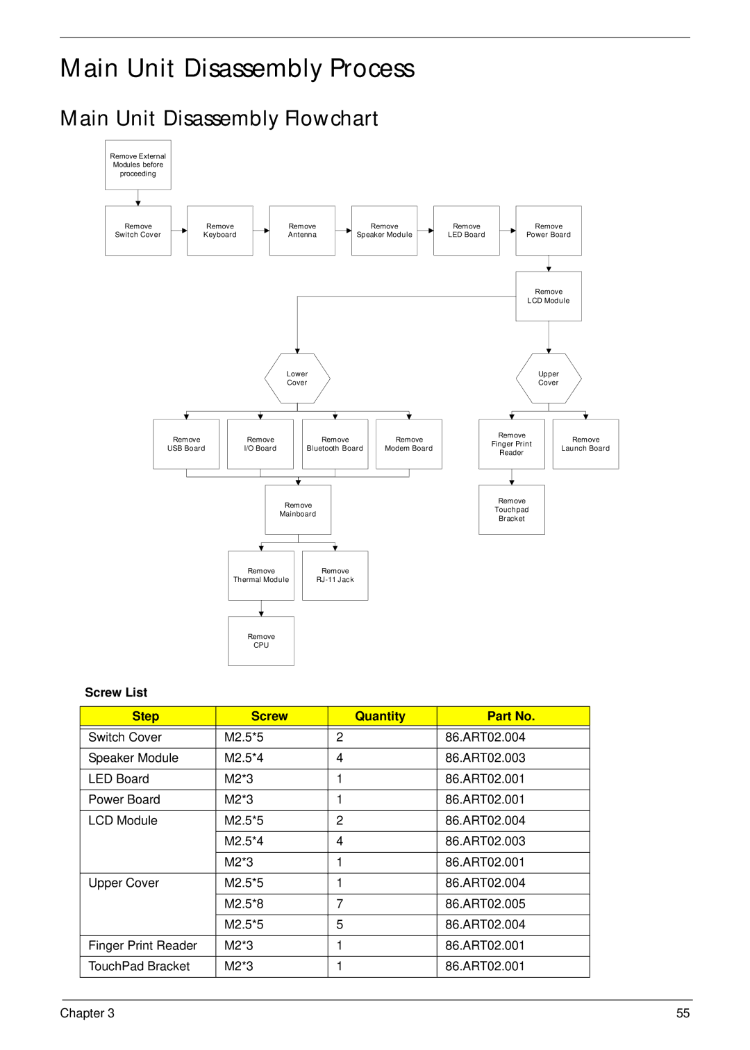
Main Unit Disassembly Process
Main Unit Disassembly Flowchart
Remove External Modules before proceeding
Remove
Switch Cover
Remove
Keyboard
Remove
Antenna
Lower
Cover
Remove
Speaker Module
Remove
LED Board
Remove
Power Board
Remove
LCD Module
Upper
Cover
Remove
USB Board
Remove |
| Remove |
| Remove | |||
I/O Board |
| Bluetooth Board |
| Modem Board | |||
|
|
|
|
|
|
|
|
|
|
|
|
|
|
|
|
Remove
Mainboard
Remove
Finger Print
Reader
Remove
Touchpad
Bracket
Remove
Launch Board
|
| Remove |
| Remove |
|
| ||
|
| Thermal Module |
|
|
| |||
|
|
|
|
|
|
|
|
|
|
|
|
|
|
|
|
|
|
|
|
|
|
|
|
|
|
|
|
| Remove |
|
|
|
|
| |
|
| CPU |
|
|
|
|
| |
Screw List |
|
|
|
|
|
|
|
|
|
|
|
|
|
|
|
| |
|
|
|
|
|
|
|
|
|
Step |
| Screw |
|
| Quantity | Part No. | ||
|
|
|
|
|
|
|
|
|
Switch Cover | M2.5*5 |
|
| 2 |
| 86.ART02.004 | ||
|
|
|
|
|
|
|
|
|
Speaker Module | M2.5*4 |
|
| 4 |
| 86.ART02.003 | ||
|
|
|
|
|
|
|
|
|
LED Board | M2*3 |
|
| 1 |
| 86.ART02.001 | ||
|
|
|
|
|
|
|
|
|
Power Board | M2*3 |
|
| 1 |
| 86.ART02.001 | ||
|
|
|
|
|
|
|
|
|
LCD Module | M2.5*5 |
|
| 2 |
| 86.ART02.004 | ||
|
|
|
|
|
|
|
|
|
| M2.5*4 |
|
| 4 |
| 86.ART02.003 | ||
|
|
|
|
|
|
|
|
|
| M2*3 |
|
| 1 |
| 86.ART02.001 | ||
|
|
|
|
|
|
|
|
|
Upper Cover | M2.5*5 |
|
| 1 |
| 86.ART02.004 | ||
|
|
|
|
|
|
|
|
|
| M2.5*8 |
|
| 7 |
| 86.ART02.005 | ||
|
|
|
|
|
|
|
|
|
| M2.5*5 |
|
| 5 |
| 86.ART02.004 | ||
|
|
|
|
|
|
|
|
|
Finger Print Reader | M2*3 |
|
| 1 |
| 86.ART02.001 | ||
|
|
|
|
|
|
|
|
|
TouchPad Bracket | M2*3 |
|
| 1 |
| 86.ART02.001 | ||
|
|
|
|
|
|
|
|
|
Chapter 3 | 55 |