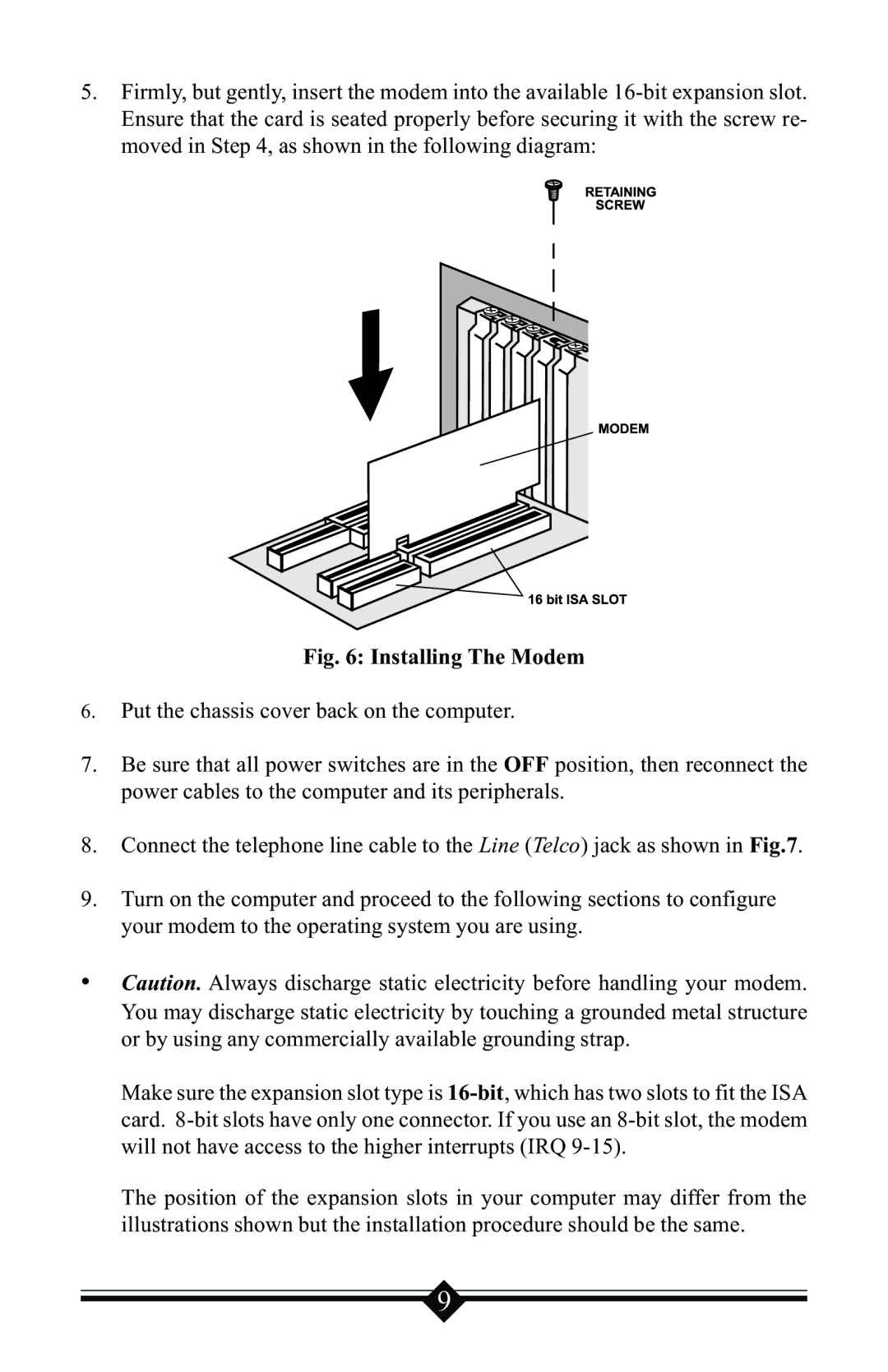
5.Firmly, but gently, insert the modem into the available
Fig. 6: Installing The Modem
6.Put the chassis cover back on the computer.
7.Be sure that all power switches are in the OFF position, then reconnect the power cables to the computer and its peripherals.
8.Connect the telephone line cable to the Line (Telco) jack as shown in Fig.7.
9.Turn on the computer and proceed to the following sections to configure your modem to the operating system you are using.
•Caution. Always discharge static electricity before handling your modem. You may discharge static electricity by touching a grounded metal structure or by using any commercially available grounding strap.
Make sure the expansion slot type is
The position of the expansion slots in your computer may differ from the illustrations shown but the installation procedure should be the same.
9
