Introduction
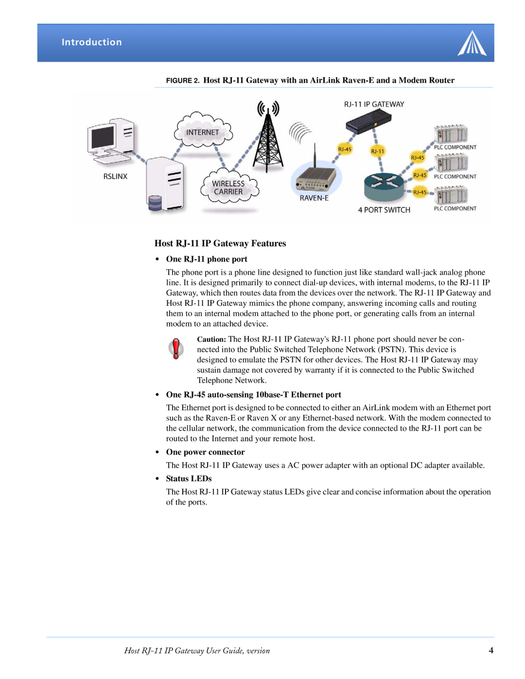
FIGURE 2. Host RJ-11 Gateway with an AirLink Raven-E and a Modem Router
Host RJ-11 IP Gateway Features
•One RJ-11 phone port
The phone port is a phone line designed to function just like standard wall-jack analog phone line. It is designed primarily to connect dial-up devices, with internal modems, to the RJ-11 IP Gateway, which then routes data from the devices over the network. The RJ-11 IP Gateway and Host RJ-11 IP Gateway mimics the phone company, answering incoming calls and routing them to an internal modem attached to the phone port, or generating calls from an internal modem to an attached device.
Caution: The Host RJ-11 IP Gateway's RJ-11 phone port should never be con- nected into the Public Switched Telephone Network (PSTN). This device is designed to emulate the PSTN for other devices. The Host RJ-11 IP Gateway may sustain damage not covered by warranty if it is connected to the Public Switched Telephone Network.
•One RJ-45 auto-sensing 10base-T Ethernet port
The Ethernet port is designed to be connected to either an AirLink modem with an Ethernet port such as the Raven-E or Raven X or any Ethernet-based network. With the modem connected to the cellular network, the communication from the device connected to the RJ-11 port can be routed to the Internet and your remote host.
•One power connector
The Host RJ-11 IP Gateway uses a AC power adapter with an optional DC adapter available.
•Status LEDs
The Host RJ-11 IP Gateway status LEDs give clear and concise information about the operation of the ports.
Host RJ-11 IP Gateway User Guide, version | 4 |