OPERATION
8. DRIVELINE ATTACHMENT |
| |||
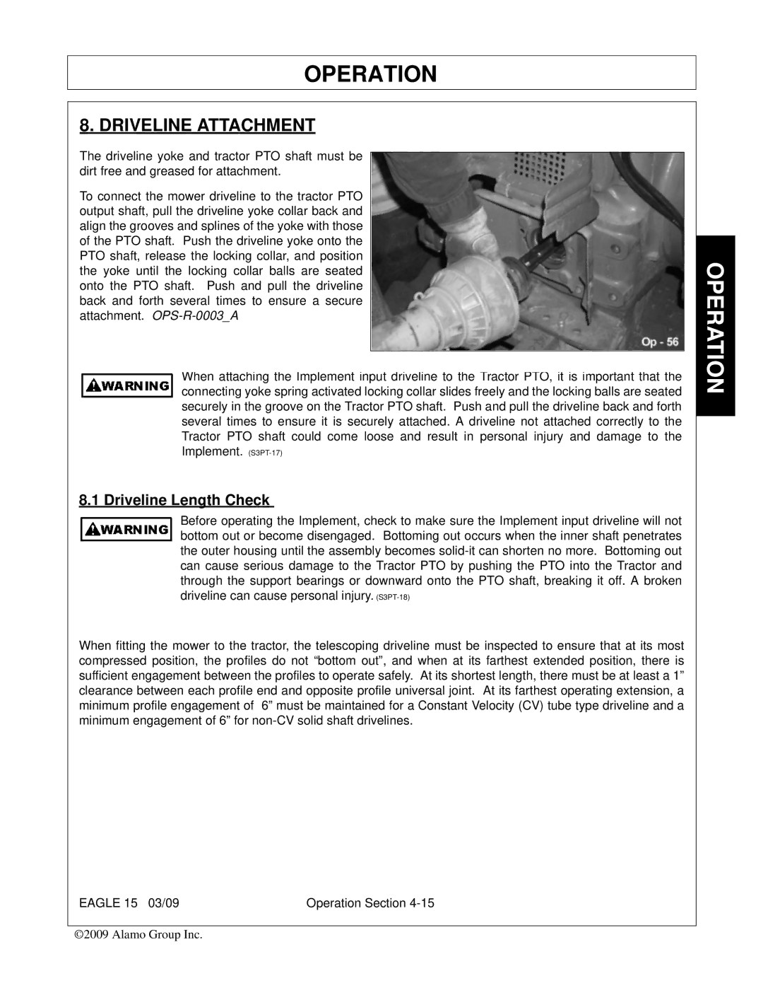
The driveline yoke and tractor PTO shaft must be |
|
|
| |
|
| |||
dirt free and greased for attachment. |
|
|
| |
To connect the mower driveline to the tractor PTO |
|
|
| |
output shaft, pull the driveline yoke collar back and |
|
|
| |
align the grooves and splines of the yoke with those |
|
|
| |
of the PTO shaft. Push the driveline yoke onto the |
|
|
|
|
|
| |||
PTO shaft, release the locking collar, and position |
|
| OPERATION | |
the yoke until the locking collar balls are seated |
|
|
| |
|
|
| ||
onto the PTO shaft. Push and pull the driveline |
|
|
| |
back and forth several times to ensure a secure |
|
|
| |
attachment. |
|
|
| |
|
|
|
| |
When attaching the Implement input driveline to the Tractor PTO, it is important that the |
| |||
connecting yoke spring activated locking collar slides freely and the locking balls are seated |
| |||
securely in the groove on the Tractor PTO shaft. Push and pull the driveline back and forth |
| |||
several times to ensure it is securely attached. A driveline not attached correctly to the |
|
| ||
|
| |||
Tractor PTO shaft could come loose and result in personal injury and damage to the |
| |||
Implement. |
| |||
8.1 Driveline Length Check |
| |||
Before operating the Implement, check to make sure the Implement input driveline will not |
| |||
bottom out or become disengaged. Bottoming out occurs when the inner shaft penetrates |
| |||
the outer housing until the assembly becomes |
| |||
can cause serious damage to the Tractor PTO by pushing the PTO into the Tractor and |
| |||
through the support bearings or downward onto the PTO shaft, breaking it off. A broken |
| |||
driveline can cause personal injury. |
| |||
When fitting the mower to the tractor, the telescoping driveline must be inspected to ensure that at its most |
| |||
compressed position, the profiles do not “bottom out”, and when at its farthest extended position, there is |
| |||
sufficient engagement between the profiles to operate safely. At its shortest length, there must be at least a 1” |
| |||
clearance between each profile end and opposite profile universal joint. At its farthest operating extension, a |
| |||
minimum profile engagement of 6” must be maintained for a Constant Velocity (CV) tube type driveline and a |
| |||
minimum engagement of 6” for |
| |||
EAGLE 15 03/09 | Operation Section |
©2009 Alamo Group Inc.