ASSEMBLY
Keep coworkers and bystanders away from the implement while filling.
13.Continue to hold the control lever until both wings are down and the wing cylinders are fully extended. Con- tinue to cycle the cylinders several times by raising and lowering the wings fully to remove any trapped air. If there is sponginess during the raising cycle, this may indicate that air is trapped in the hydraulic circuit. Continue to cycle the cylinders until all sponginess is removed.
14.Test to make sure the wings lower slowly when they are allowed to float down and are not powered down. This is a safety feature built into the system. If the wings fall rapidly, have the hydraulic system or cylinders repaired before operating the implement.
CONNECTING DRIVELINE
DO NOT use a PTO adapter to attach a
(S3PT-14)
When attaching the Implement input driveline to the Tractor PTO, it is important that the connecting yoke spring activated locking collar slides freely and the locking balls are seated securely in the groove on the Tractor PTO shaft. Push and pull the driveline back and forth several times to ensure it is securely attached. A driveline not attached correctly to the Tractor PTO shaft could come loose and result in personal injury and damage to the Implement.
DRIVELINE ATTACHMENT
The driveline yoke and tractor PTO shaft must be dirt free and greased for attachment.
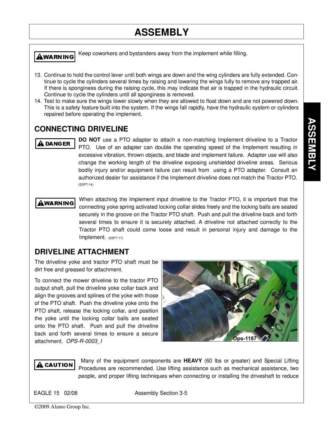
To connect the mower driveline to the tractor PTO output shaft, pull the driveline yoke collar back and align the grooves and splines of the yoke with those of the PTO shaft. Push the driveline yoke onto the PTO shaft, release the locking collar, and position the yoke until the locking collar balls are seated onto the PTO shaft. Push and pull the driveline back and forth several times to ensure a secure
attachment.
Many of the equipment components are HEAVY (60 lbs or greater) and Special Lifting Procedures are recommended. Use lifting assistance such as mechanical assistance, two people, and proper lifting techniques when connecting or installing the driveshaft to reduce
EAGLE 15 02/08 | Assembly Section |
©2009 Alamo Group Inc.
