Alamo Eagle 14, Eagle 20 manual Counterweight Attachment, Driveline Attachment

Models: Eagle 14 Eagle 20

1 186
Download 186 pages 63.63 Kb
Page 97
Image 97

ASSEMBLY

Counterweight Attachment

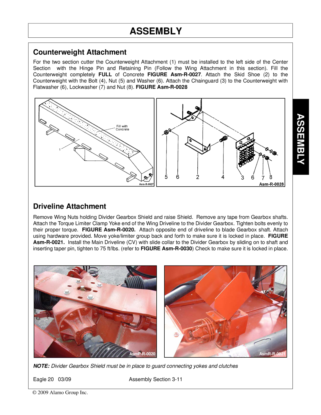
For the two section cutter the Counterweight Attachment (1) must be installed to the left side of the Center Section with the Hinge Pin and Retaining Pin (Follow the Wing Attachment in this section). Fill the Counterweight completely FULL of Concrete FIGURE Asm-R-0027. Attach the Skid Shoe (2) to the Counterweight with the Bolt (4), Nut (5) and Washer (6). Attach the Chainguard (3) to the Counterweight with Flatwasher (6), Lockwasher (7) and Nut (8). FIGURE Asm-R-0028

Driveline Attachment

Remove Wing Nuts holding Divider Gearbox Shield and raise Shield. Remove any tape from Gearbox shafts. Attach the Torque Limiter Clamp Yoke end of the Wing Driveline to the Divider Gearbox. Tighten bolts evenly to their proper torque. FIGURE Asm-R-0020.Attach opposite end of driveline to blade Gearbox shaft. Attach using hardware provided. Move yoke/limiter group back and forth to make sure it is locked in place. FIGURE Asm-R-0021.Install the Main Driveline (CV) with slide collar to the Divider Gearbox by sliding on to shaft and inserting taper pin, tighten to 75 ft/lbs. (refer to FIGURE Asm-R-0030) Check to make sure it is locked in place.

NOTE: Divider Gearbox Shield must be in place to guard connecting yokes and clutches

Eagle 20 03/09

Assembly Section 3-11

© 2009 Alamo Group Inc.

ASSEMBLY

Page 97
Image 97
Alamo Eagle 14, Eagle 20 manual Counterweight Attachment, Driveline Attachment