Pump & Drive Shaft Installation:
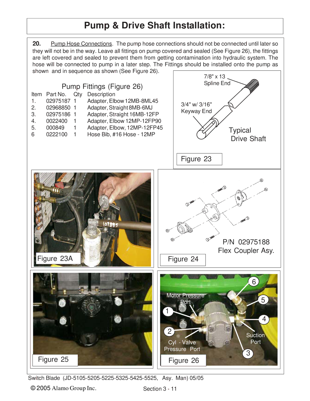
20.Pump Hose Connections. The pump hose connections should not be connected until later so they will not be in the way. Leave all fittings on pump covered and sealed (See Figure 26), the fittings are left covered and sealed to prevent them from getting contamination into hydraulic system. The hose will be connected to pump in a later step. The Fittings should be installed onto the pump as
shown and in sequence as shown (See Figure 26).
|
|
|
| 7/8" x 13 | |
| Pump Fittings (Figure 26) | Spline End | |||
|
| ||||
Item | Part No. | Qty | Description |
| |
1. | 02975187 | 1 | Adapter, Elbow | 3/4" w/ 3/16" | |
2. | 02968850 | 1 | Adapter, Straight | ||
Keyway End | |||||
3. | 02975186 | 1 | Adapter, Straight | ||
| |||||
4. | 0022400 | 1 | Adapter, Elbow |
| |
5. | 000849 | 1 | Adapter, Elbow, | Typical | |
6 | 0222100 | 1 | Hose Bib, #16 Hose - 12MP | Drive Shaft | |
|
|
|
| ||
Figure 23
|
|
|
|
|
|
|
|
|
|
| P/N 02975188 |
|
|
|
|
|
|
|
|
|
|
|
| Flex Coupler Asy. |
|
|
|
|
| Figure 23A |
|
|
|
| Figure 24 |
|
| |
|
|
|
|
|
|
|
|
|
|
|
|
|
|
|
|
|
|
|
|
|
|
|
|
|
|
|
|
|
|
|
|
|
|
|
|
|
|
|
|
|
|
|
|
|
|
|
|
|
| 6 |
|
|
|
|
|
|
|
|
|
|
| Motor Pressure | 5 |
|
|
|
|
|
|
|
|
|
|
| Port |
| |
|
|
|
|
|
|
|
|
| 1 | 4 |
| |
|
|
|
|
|
|
|
|
|
|
|
| |
|
|
|
|
|
|
|
|
| 2 | Suction |
| |
|
|
|
|
|
|
|
|
|
|
|
| |
|
|
|
|
|
|
|
|
|
| Cyl - Valve | Port |
|
|
|
|
|
|
|
|
|
|
| Pressure Port | 3 |
|
|
|
|
|
|
|
|
|
|
|
|
| |
|
|
|
| Figure 25 |
|
|
|
|
| Figure 26 |
| |
|
|
|
|
|
|
|
|
|
|
| ||
|
|
|
|
|
|
|
|
|
|
|
| |
|
|
|
|
|
|
|
|
|
|
|
|
|
|
|
|
|
|
|
|
|
|
|
|
|
|
|
|
|
|
|
|
|
|
|
|
|
|
|
Switch Blade |
|
| ||||||||||
| © 2005 Alamo Group Inc. | Section 3 - 11 |
|
| ||||||||
