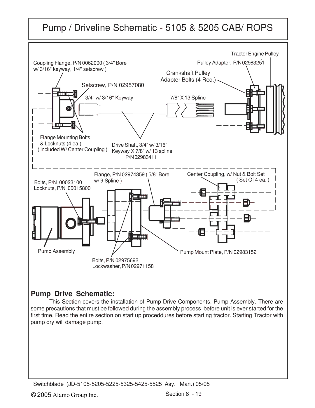
Pump / Driveline Schematic - 5105 & 5205 CAB/ ROPS
Coupling Flange, P/N 0062000 ( 3/4" Bore w/ 3/16" keyway, 1/4" setscrew )
Tractor Engine Pulley
Pulley Adapter, P/N 02983251
Crankshaft Pulley
Adapter Bolts (4 Req.)
Setscrew, P/N 02957080 |
| |
3/4" w/ 3/16" Keyway | 7/8" X 13 Spline | |
Flange Mounting Bolts |
|
|
& Locknuts (4 ea.) | Drive Shaft, 3/4" w/ 3/16" |
|
( Included W/ Center Coupling ) Keyway X 7/8" w/ 13 spline | ||
| P/N 02983411 |
|
| Flange, P/N 02974359 ( 5/8" Bore | Center Coupling, w/ Nut & Bolt Set |
Bolts, P/N 00023100 | w/ 9 Spline ) | ( Set Of 4 ea. ) |
Locknuts, P/N 00015800 |
|
|
Pump Assembly |
| Pump Mount Plate, P/N 02983152 |
| Bolts, P/N 02975692 |
|
| Lockwasher, P/N 02971158 |
|
Pump Drive Schematic:
This Section covers the installation of Pump Drive Components, Pump Assembly. There are some precautions that must be followed during the assembly process before unit is ever started for the first time, Read the entire section on start up proceddures before starting tractor. Starting Tractor with pump dry will damage pump.
Switchblade
© 2005 Alamo Group Inc. | Section 8 - 19 |