Pump & Drive Shaft Installation:
Pump & Drive Shaft Installation:
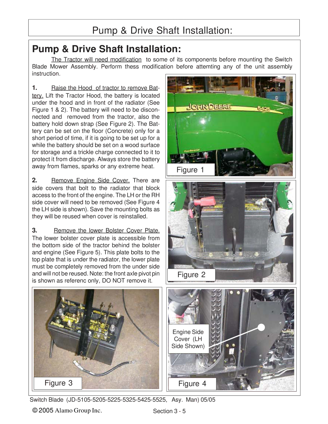
The Tractor will need modification to some of its components before mounting the Switch Blade Mower Assembly. Perform thess modification before attemting any of the unit assembly instruction.
1.Raise the Hood of tractor to remove Bat- tery. Lift the Tractor Hood, the battery is located under the hood and in front of the radiator (See Figure 1 & 2). The battery will need to be discon- nected and removed from the tractor, also the battery hold down strap (See Figure 2). The Bat- tery can be set on the floor (Concrete) only for a short period of time, if it is going to be set up for a while the battery should be set on a wood surface for storage and a trickle charge connected to it to protect it from discharge. Always store the battery
away from flames, sparks or any extreme heat. |
| Figure 1 |
| |
|
|
|
| |
2. | Remove Engine Side Cover. There are |
|
|
|
|
|
| ||
|
|
| ||
|
|
| ||
side covers that bolt to the radiator that block |
|
|
| |
access to the front of the engine. The LH or the RH |
|
|
| |
side cover will need to be removed (See Figure 4 |
|
|
| |
the LH side is shown). Save the mounting bolts as |
|
|
| |
they will be reused when cover is reinstalled. |
|
|
| |
3. | Remove the lower Bolster Cover Plate. |
|
|
|
The lower bolster cover plate is accessible from |
|
|
| |
the bottom side of the tractor behind the bolster |
|
|
| |
and engine (See Figure 5). This plate bolts to the |
|
|
| |
top plate that is under the radiator, the lower plate |
|
|
| |
must be completely removed from the under side |
|
|
| |
and will not be reused. Note: the front axle pivot pin |
| Figure 2 |
| |
is shown as referenc only, DO NOT remove it. |
|
|
| |
|
|
| ||
Engine Side
Cover (LH
Side Shown)
Figure 3
Figure 4
Switch Blade
© 2005 Alamo Group Inc. | Section 3 - 5 |
