Control Valve & Valve Controls Installation
Item | Part No. | Qty. | Description | Item | Part No. | Qty. | Description |
| 02982077 | Valve Asy. W/ Fittings | 21. | 02976946 | 1 | Cap Asy. | |
| 02974306 | Valve Asy. W/O Fittings 22. | 02976945 | 4 | Spring | ||
1. | 02976934 | 2 | Unload Plunger | 23. | 02966669 | 1 | Spring |
2. | 02966645 | 2 | Poppet Asy. | 24. | 02976944 | 2 | Plug Asy. |
3. | 02966646 | 1 | Spacer | 25. | 02976943 | 1 | Washer |
4. | 02976933 | 2 | Spool | 26. | 02976942 | 1 | Washer |
5. | 02966648 | 4 | Seat Asy. | 27. | 02976941 | 3 | Ball |
6. | 02966649 | 2 | Plug Asy. | 28. | 02976940 | 1 | Spring |
7. | 02966650 | 2 | Plug Asy. | 29. | 02976939 | 1 | Spring |
8. | 02966651 | 2 | Bushing | 30. | 02976938 | 1 | Cone |
9. | 02966652 | 2 | Lockout Spring | 31. | 02976937 | 1 | Spacer |
10. | 02966653 | 1 | Cap Asy. | 32. | 02976936 | 1 | Adapter Cap |
11. | 02966654 | 1 | Plug Asy. | 33. | 02976935 | A/R | Washer |
12. | 02976932 | 1 | Body | 34. | 02966671 | 2 | Wiper Seal |
13. | 02976931 | 1 | Poppet | 35. | 02976957 | 2 | Handle Kit |
14. | 02976930 | 1 | Seat | 36. | 02968850 | 2 | Adapter,Straight |
15. | 02966657 | 4 |
|
|
| 8MB - 6MJ | |
16. | 02966658 | 2 | Retaining Ring | 37. | 03200284 | 2 | Adapter,Straight |
17. | 02966659 | A/R | Washer |
|
|
| 6MB - 4MJ |
18. | 02966660 | A/R | Washer | 38. | 02965166 | 2 | Adapter,Tee |
19. | 02966661 | A/R | Washer |
|
|
| 6FJX - 6MJ - 6MJ |
20. | 02966662 | 1 | Washer | 39. | 02982479 | 2 | Adapter, Straight |
Two Spool Control Valve: |
|
|
| 4MB - 6FJX | |||
|
|
|
| ||||
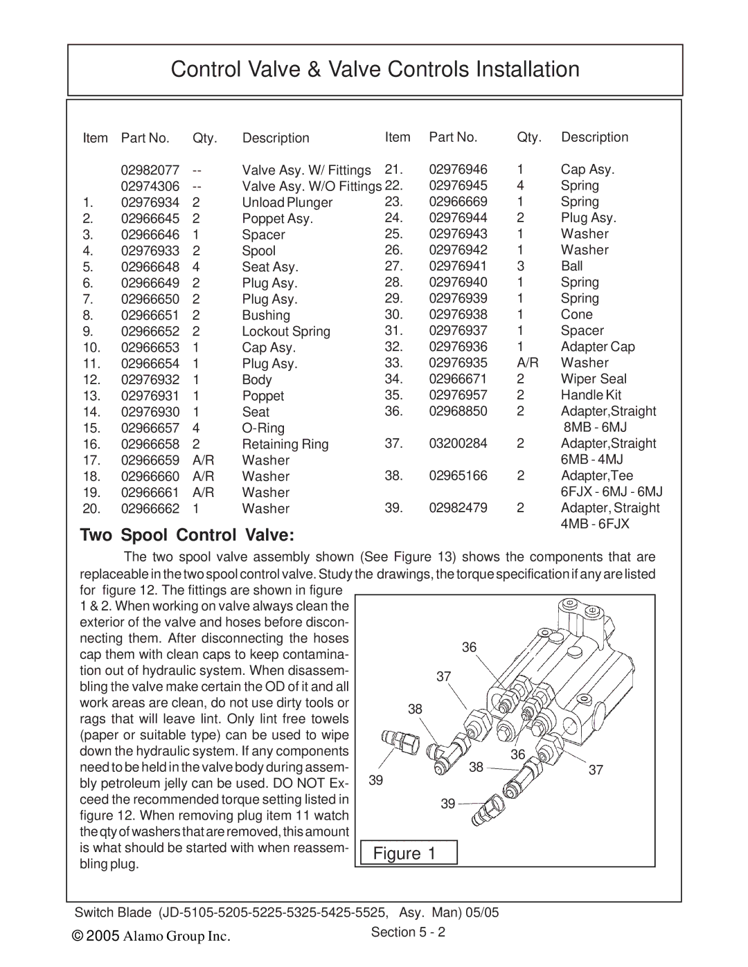
The two spool valve assembly shown (See Figure 13) shows the components that are replaceable in the two spool control valve. Study the drawings, the torque specification if any are listed
for figure 12. The fittings are shown in figure |
|
|
|
|
|
|
1 & 2. When working on valve always clean the |
|
|
|
|
|
|
exterior of the valve and hoses before discon- |
|
|
|
|
|
|
necting them. After disconnecting the hoses | 36 |
|
|
| ||
cap them with clean caps to keep contamina- |
|
|
| |||
|
|
|
|
|
| |
tion out of hydraulic system. When disassem- | 37 |
|
|
|
| |
bling the valve make certain the OD of it and all |
|
|
|
| ||
|
|
|
|
|
| |
work areas are clean, do not use dirty tools or | 38 |
|
|
|
| |
rags that will leave lint. Only lint free towels |
|
|
|
| ||
|
|
|
|
|
| |
(paper or suitable type) can be used to wipe |
|
|
|
|
|
|
down the hydraulic system. If any components | 38 |
| 36 |
| ||
need to be held in the valve body during assem- |
| 37 |
| |||
bly petroleum jelly can be used. DO NOT Ex- | 39 |
|
|
|
| |
ceed the recommended torque setting listed in | 39 |
|
|
|
| |
figure 12. When removing plug item 11 watch |
|
|
|
|
|
|
the qty of washers that are removed, this amount |
|
|
|
|
|
|
is what should be started with when reassem- |
| Figure 1 |
|
|
|
|
bling plug. |
|
|
|
|
|
|
|
|
|
|
|
| |
|
|
|
|
|
| |
|
|
|
|
|
|
|
Switch Blade |
|
| ||||
© 2005 Alamo Group Inc. |
| Section 5 - 2 |
|
| ||