Versatis_Conference_uk.qxd 31/03/2005 16:03 Page 28
28
2. INSTALLATION
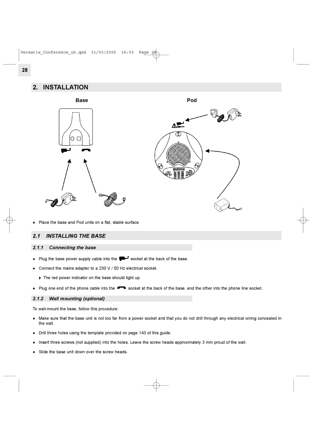
Base | Pod |
lPlace the base and Pod units on a flat, stable surface.
2.1INSTALLING THE BASE
2.1.1Connecting the base
l Plug the base power supply cable into the ![]() socket at the back of the base.
socket at the back of the base.
lConnect the mains adapter to a 230 V / 50 Hz electrical socket.
"The red power indicator on the base should light up.
lPlug one end of the phone cable into the ![]() socket at the back of the base, and the other into the phone line socket.
socket at the back of the base, and the other into the phone line socket.
2.1.2Wall mounting (optional)
To
lMake sure that the base unit is not too far from a power socket and that you do not drill through any electrical wiring concealed in the wall.
lDrill three holes using the template provided on page 143 of this guide.
lInsert three screws (not supplied) into the holes. Leave the screw heads approximately 3 mm proud of the wall.
lSlide the base unit down over the screw heads.