TOP PANEL FEATURES
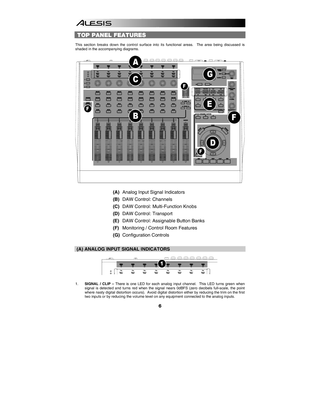
This section breaks down the control surface into its functional areas. The area being discussed is shaded in the accompanying diagrams.
A |
|
C | G |
| |
| F |
F | E |
| |
B | F |
| D |
| F |
(A)Analog Input Signal Indicators
(B)DAW Control: Channels
(C)DAW Control:
(D)DAW Control: Transport
(E)DAW Control: Assignable Button Banks
(F)Monitoring / Control Room Features
(G)Configuration Controls
(A)ANALOG INPUT SIGNAL INDICATORS
1 |
1.SIGNAL / CLIP – There is one LED for each analog input channel. This LED turns green when signal is detected and turns red when the signal nears 0dBFS (zero decibels
6